Sabtu, 30 Juli 2011

3G LTE Tutorial - 3GPP Long Term Evolution

3G LTE is now being deployed and is the way forwards for high speed cellular services.

There has been a rapid increase in the use of data carried by cellular services, and this increase will only become larger in what has been termed the "data explosion". To cater for this and the increased demands for increased data transmission speeds and lower latency, further development of cellular technology have been required.

The UMTS cellular technology upgrade has been dubbed LTE - Long Term Evolution. The idea is that 3G LTE will enable much higher speeds to be achieved along with much lower packet latency (a growing requirement for many services these days), and that 3GPP LTE will enable cellular communications services to move forward to meet the needs for cellular technology to 2017 and well beyond.

Many operators have not yet upgraded their basic 3G networks, and 3GPP LTE is seen as the next logical step for many operators, who will leapfrog straight from basic 3G straight to LTE as this will avoid providing several stages of upgrade. The use of LTE will also provide the data capabilities that will be required for many years and until the full launch of the full 4G standards known as LTE Advanced.


3G LTE evolution

Although there are major step changes between LTE and its 3G predecessors, it is nevertheless looked upon as an evolution of the UMTS / 3GPP 3G standards. Although it uses a different form of radio interface, using OFDMA / SC-FDMA instead of CDMA, there are many similarities with the earlier forms of 3G architecture and there is scope for much re-use.

LTE can be seen for provide a further evolution of functionality, increased speeds and general improved performance.

WCDMA
(UMTS)
HSPA
HSDPA / HSUPA
HSPA+ LTE
Max downlink speed
bps
384 k 14 M 28 M 100M
Max uplink speed
bps
128 k 5.7 M 11 M 50 M
Latency
round trip time
approx
150 ms 100 ms 50ms (max) ~10 ms
3GPP releases Rel 99/4 Rel 5 / 6 Rel 7 Rel 8
Approx years of initial roll out 2003 / 4 2005 / 6 HSDPA
2007 / 8 HSUPA
2008 / 9 2009 / 10
Access methodology CDMA CDMA CDMA OFDMA / SC-FDMA

In addition to this, LTE is an all IP based network, supporting both IPv4 and IPv6. There is also no basic provision for voice, although this can be carried as VoIP.


3GPP LTE technologies

LTE has introduced a number of new technologies when compared to the previous cellular systems. They enable LTE to be able to operate more efficiently with respect to the use of spectrum, and also to provide the much higher data rates that are being required.

  • OFDM (Orthogonal Frequency Division Multiplex): OFDM technology has been incorporated into LTE because it enables high data bandwidths to be transmitted efficiently while still providing a high degree of resilience to reflections and interference. The access schemes differ between the uplink and downlink: OFDMA (Orthogonal Frequency Division Multiple Access is used in the downlink; while SC-FDMA(Single Carrier - Frequency Division Multiple Access) is used in the uplink. SC-FDMA is used in view of the fact that its peak to average power ratio is small and the more constant power enables high RF power amplifier efficiency in the mobile handsets - an important factor for battery power equipment. Read more about LTE OFDM / OFDMA / SCFMDA
  • MIMO (Multiple Input Multiple Output): One of the main problems that previous telecommunications systems has encountered is that of multiple signals arising from the many reflections that are encountered. By using MIMO, these additional signal paths can be used to advantage and are able to be used to increase the throughput.

    When using MIMO, it is necessary to use multiple antennas to enable the different paths to be distinguished. Accordingly schemes using 2 x 2, 4 x 2, or 4 x 4 antenna matrices can be used. While it is relatively easy to add further antennas to a base station, the same is not true of mobile handsets, where the dimensions of the user equipment limit the number of antennas which should be place at least a half wavelength apart. Read more about LTE MIMO
  • SAE (System Architecture Evolution): With the very high data rate and low latency requirements for 3G LTE, it is necessary to evolve the system architecture to enable the improved performance to be achieved. One change is that a number of the functions previously handled by the core network have been transferred out to the periphery. Essentially this provides a much "flatter" form of network architecture. In this way latency times can be reduced and data can be routed more directly to its destination. Read more about LTE SAE

These technologies are addressed in much greater detail in the following pages of this tutorial.

3G LTE specification overview

It is worth summarizing the key parameters of the 3G LTE specification. In view of the fact that there are a number of differences between the operation of the uplink and downlink, these naturally differ in the performance they can offer.

Parameter Details
Peak downlink speed
64QAM
(Mbps)
100 (SISO), 172 (2x2 MIMO), 326 (4x4 MIMO)
Peak uplink speeds
(Mbps)
50 (QPSK), 57 (16QAM), 86 (64QAM)
Data type All packet switched data (voice and data). No circuit switched.
Channel bandwidths
(MHz)
1.4, 3, 5, 10, 15, 20
Duplex schemes FDD and TDD
Mobility 0 - 15 km/h (optimised),
15 - 120 km/h (high performance)
Latency Idle to active less than 100ms
Small packets ~10 ms
Spectral efficiency Downlink: 3 - 4 times Rel 6 HSDPA
Uplink: 2 -3 x Rel 6 HSUPA
Access schemes OFDMA (Downlink)
SC-FDMA (Uplink)
Modulation types supported QPSK, 16QAM, 64QAM (Uplink and downlink)

These highlight specifications give an overall view of the performance that LTE will offer. It meets the requirements of industry for high data download speeds as well as reduced latency - a factor important for many applications from VoIP to gaming and interactive use of data. It also provides significant improvements in the use of the available spectrum.

LTE Security

LTE security is an issue that is of paramount importance. It is necessary to ensure that LTE security measures provide the level of security required without impacting the user as this could drive users away.

Nevertheless with the level of sophistication of security attacks growing, it is necessary to ensure that LTE security allows users to operate freely and without fear of attack from hackers. Additionally the network must also be organised in such a way that it is secure against a variety of attacks.


LTE security basics

When developing the LTE security elements there were several main requirements that were borne in mind:

  • LTE security had to provide at least the same level of security that was provided by 3G services.
  • The LTE security measures should not affect user convenience.
  • The LTE security measures taken should provide defence from attacks from the Internet.
  • The security functions provided by LTE should not affect the transition from existing 3G services to LTE.
  • The USIM currently used for 3G services should still be used.

To ensure these requirements for LTE security are met, it has been necessary to add further measures into all areas of the system from the UE through to the core network.

The main changes that have been required to implement the required level of LTE security are summarised below:

  • A new hierarchical key system has been introduced in which keys can be changed for different purposes.
  • The LTE security functions for the Non-Access Stratum, NAS, and Access Stratum, AS have been separated. The NAS functions are those functions for which the processing is accomplished between the core network and the mobile terminal or UE. The AS functions encompass the communications between the network edge, i.e. the Evolved Node B, eNB and the UE.
  • The concept of forward security has been introduced for LTE security.
  • LTE security functions have been introduced between the existing 3G network and the LTE network.

LTE USIM

One of the key elements within the security of GSM, UMTS and now LTE was the concept of the subscriber identity module, SIM. This card carried the identity of the subscriber in an encrypted fashion and this could allow the subscriber to keep their identity while transferring or upgrading phones.

With the transition form 2G - GSM to 3G - UMTS, the idea of the SIM was upgraded and a USIM - UMTS Subscriber Identity Module, was used. This gave more functionality, had a larger memory, etc.

For LTE, only the USIM may be used - the older SIM cards are not compatible and may not be used.

Voice over LTE - VoLTE

The Voice over LTE scheme was devised as a result of operators seeking a standardised system for transferring voice traffic over LTE. Originally LTE was seen as a completely IP cellular system just for carrying data, and operators would be able to carry voice either by reverting to 2G / 3G systems or by using VoIP.

Operators, however saw the fact that a voice format was not defined as a major omission for the system. It was seen that the lack of standardisation may provide problems with scenarios including roaming. In addition to this, SMS is a key requirement. It is not often realised, that SMS is used to set-up many mobile broadband connections, and a lack of SMS is seen as a show-stopper by many.

As mobile operators receive over 80% of their revenues from voice and SMS traffic, it is necessary to have a viable and standardized scheme to provide these services and protect this revenue.


Options for Voice over LTE

When looking at the options for ways of carrying voice over LTE, a number of possible solutions were investigated. A number of alliances were set up to promote different ways of providing the service. A number of systems were prosed as outlined below:

  • VoLGA, Voice over LTE via GAN
  • CSFB, Circuit Switched Fall Back
  • One Voice / later called Voice over LTE, VoLTE

Issues for Voice services over LTE

Unlike previous cellular telecommunications standards including GSM, LTE does not have dedicated channels for circuit switched telephony. Instead LTE is an all-IP system providing an end-to-end IP connection from the mobile equipment to the core network and out again.

In order to provide some form of voice connection over a standard LTE bearer, some form of Voice over IP, VoIP must be used.

The aim for any voice service is to utilise the low latency and QoS features available within LTE to ensure that any voice service offers an improvement over the standards available on the 2G and 3G networks.


VoLGA

The VoLGA standard was based on the existing 3GPP Generic Access Network (GAN) standard, and the aim was to enable LTE users to receive a consistent set of voice, SMS (and other circuit-switched) services as they transition between GSM, UMTS and LTE access networks.

For mobile operators, the aim of VoLGA was to provide a low-cost and low-risk approach for bringing their primary revenue generating services (voice and SMS) onto the new LTE network deployments.


CSFB, Circuit Switched Fall Back

The circuit switched fall-back, CSFB option for providing voice over LTE has been standardised under 3GPP specification 23.272. Essentially LTE CSFB uses a variety of processes and network elements to enable the circuit to fall back to the 2G or 3G connection before a circuit switched call is initiated.

The specification also allows for SMS to be carried as this is essential for very many set-up procedures for cellular telecommunications. To achieve this the handset uses an interface known as SGs which allows messages to be sent over an LTE channel. The

In addition to this CSFB requires modification to elements within the network, in particular the MSCs as well as support, obviously on new devices. MSC modifications are also required for the SMS over SGs facilities. For CSFB, this is required from the initial launch of CSFB in view of the criticality of SMS for many procedures.


Voice over LTE, VoLTE basics

The One Voice profile for Voice over LTE, VoLTE was developed by a collaboration between over forty operators including: AT&T, Verizon Wireless, Nokia and Alcatel-Lucent.

At the 2010 GSMA Mobile World Congress, GSMA announced that they were supporting the One Voice solution to provide Voice over LTE.

VoLTE, Voice over LTE is an IMS-based specification. Adopting this approach will enable it to integrate into the suite of applications that will become available on LTE.

To provide the VoLTE service, three interfaces are being defined:

  • User Network interface, UNI: This interface is located between the user's equipment and the operators network.
  • Roaming Network Network Interface, R-NNI: The R-NNI is an interface located between the Home and Visited Network. This is used for a user that is not attached to their Home network, i.e. roaming.
  • Interconnect Network Network Interface, I-NNI: The I-NNI is the interface located between the networks of the two parties making a call.

Work on the definition of VoLTE, Voice over LTE is ongoing. It will include a variety of elements including some of the following:

  • It will be necessary to ensure the continuity of Voice calls when a user moves from an LTE coverage area to another where a fallback to another technology is required. This form of handover will be achieved using Single Radio Voice Call Continuity, or SR-VCC).
  • It will be important to provide the optimal routing of bearers for voice calls when customers are roaming.
  • Another area of importance will be to establish commercial frameworks for roaming and interconnect for services implemented using VoLTE definitions. This will enable roaming agreements to be set up.
  • Provision of capabilities associated with the model of roaming hubbing.
  • For any services, including LTE, it is necessary to undertake a thorough security and fraud threat audit to prevent hacking and un-authorised entry into any area within the network..

In many ways the implementation of VoLTE at a high level is straightforward. The handset or phone needs to have software loaded to provide the VoLTE functionality. This can be in the form of an App.

The network then requires to be IMS compatible.

While this may appear straightforward, there are many issues for this to be made operational, especially via the vagaries of the radio access network where time delays and propagation anomalies add considerably to the complexity.

LTE SAE System Architecture Evolution

Along with 3G LTE - Long Term Evolution that applies more to the radio access technology of the cellular telecommunications system, there is also an evolution of the core network. Known as SAE - System Architecture Evolution. This new architecture has been developed to provide a considerably higher level of performance that is in line with the requirements of LTE.

As a result it is anticipated that operators will commence introducing hardware conforming to the new System Architecture Evolution standards so that the anticipated data levels can be handled when 3G LTE is introduced.

The new SAE, System Architecture Evolution has also been developed so that it is fully compatible with LTE Advanced, the new 4G technology. Therefore when LTE Advanced is introduced, the network will be able to handle the further data increases with little change.


Reason for SAE System Architecture Evolution

The SAE System Architecture Evolution offers many advantages over previous topologies and systems used for cellular core networks. As a result it is anticipated that it will be wide adopted by the cellular operators.

SAE System Architecture Evolution will offer a number of key advantages:

  1. Improved data capacity: With 3G LTE offering data download rates of 100 Mbps, and the focus of the system being on mobile broadband, it will be necessary for the network to be able to handle much greater levels of data. To achieve this it is necessary to adopt a system architecture that lends itself to much grater levels of data transfer.
  2. All IP architecture: When 3G was first developed, voice was still carried as circuit switched data. Since then there has been a relentless move to IP data. Accordingly the new SAE, System Architecture Evolution schemes have adopted an all IP network configuration.
  3. Reduced latency: With increased levels of interaction being required and much faster responses, the new SAE concepts have been evolved to ensure that the levels of latency have been reduced to around 10 ms. This will ensure that applications using 3G LTE will be sufficiently responsive.
  4. Reduced OPEX and CAPEX: A key element for any operator is to reduce costs. It is therefore essential that any new design reduces both the capital expenditure (CAPEX)and the operational expenditure (OPEX). The new flat architecture used for SAE System Architecture Evolution means that only two node types are used. In addition to this a high level of automatic configuration is introduced and this reduces the set-up and commissioning time.

SAE System Architecture Evolution basics

The new SAE network is based upon the GSM / WCDMA core networks to enable simplified operations and easy deployment. Despite this, the SAE network brings in some major changes, and allows far more efficient and effect transfer of data.

There are several common principles used in the development of the LTE SAE network:

  • a common gateway node and anchor point for all technologies.
  • an optimised architecture for the user plane with only two node types.
  • an all IP based system with IP based protocols used on all interfaces.
  • a split in the control / user plane between the MME, mobility management entity and the gateway.
  • a radio access network / core network functional split similar to that used on WCDMA / HSPA.
  • integration of non-3GPP access technologies (e.g. cdma2000, WiMAX, etc) using client as well as network based mobile-IP.

The main element of the LTE SAE network is what is termed the Evolved Packet Core or EPC. This connects to the eNodeBs as shown in the diagram below.

LTE SAE Evolved Packet Core

As seen within the diagram, the LTE SAE Evolved Packet Core, EPC consists of four main elements as listed below:

  • Mobility Management Entity, MME: The MME is the main control node for the LTE SAE access network, handling a number of features:
    • Idle mode UE tracking
    • Bearer activation / de-activation
    • Choice of SGW for a UE
    • Intra-LTE handover involving core network node location
    • Interacting with HSS to authenticate user on attachment and implements roaming restrictions
    • It acts as a termination for the Non-Access Stratum (NAS)
    • Provides temporary identities for UEs
    • The SAE MME acts the termination point for ciphering protection for NAS signaling. As part of this it also handles the security key management. Accordingly the MME is the point at which lawful interception of signalling may be made.
    • Paging procedure
    • The S3 interface terminates in the MME thereby providing the control plane function for mobility between LTE and 2G/3G access networks.
    • The SAE MME also terminates the S6a interface for the home HSS for roaming UEs.
    It can therefore be seen that the SAE MME provides a considerable level of overall control functionality.
  • Serving Gateway, SGW: The Serving Gateway, SGW, is a data plane element within the LTE SAE. Its main purpose is to manage the user plane mobility and it also acts as the main border between the Radio Access Network, RAN and the core network. The SGW also maintains the data paths between the eNodeBs and the PDN Gateways. In this way the SGW forms a interface for the data packet network at the E-UTRAN.

    Also when UEs move across areas served by different eNodeBs, the SGW serves as a mobility anchor ensuring that the data path is maintained.
  • PDN Gateway, PGW: The LTE SAE PDN gateway provides connectivity for the UE to external packet data networks, fulfilling the function of entry and exit point for UE data. The UE may have connectivity with more than one PGW for accessing multiple PDNs.
  • Policy and Charging Rules Function, PCRF: This is the generic name for the entity within the LTE SAE EPC which detects the service flow, enforces charging policy. For applications that require dynamic policy or charging control, a network element entitled the Applications Function, AF is used.

    LTE SAE PCRF Interfaces


    LTE SAE PCRF Interfaces

LTE SAE Distributed intelligence

In order that requirements for increased data capacity and reduced latency can be met, along with the move to an all-IP network, it is necessary to adopt a new approach to the network structure.

For 3G UMTS / WCDMA the UTRAN (UMTS Terrestrial Radio Access Network, comprising the Node B's or basestations and Radio Network Controllers) employed low levels of autonomy. The Node Bs were connected in a star formation to the Radio Network Controllers (RNCs) which carried out the majority of the management of the radio resource. In turn the RNCs connected to the core network and connect in turn to the Core Network.

To provide the required functionality within LTE SAE, the basic system architecture sees the removal of a layer of management. The RNC is removed and the radio resource management is devolved to the base-stations. The new style base-stations are called eNodeBs or eNBs.

The eNBs are connected directly to the core network gateway via a newly defined "S1 interface". In addition to this the new eNBs also connect to adjacent eNBs in a mesh via an "X2 interface". This provides a much greater level of direct interconnectivity. It also enables many calls to be routed very directly as a large number of calls and connections are to other mobiles in the same or adjacent cells. The new structure allows many calls to be routed far more directly and with only minimum interaction with the core network.

In addition to the new Layer 1 and Layer 2 functionality, eNBs handle several other functions. This includes the radio resource control including admission control, load balancing and radio mobility control including handover decisions for the mobile or user equipment (UE).

The additional levels of flexibility and functionality given to the new eNBs mean that they are more complex than the UMTS and previous generations of base-station. However the new 3G LTE SAE network structure enables far higher levels of performance. In addition to this their flexibility enables them to be updated to handle new upgrades to the system including the transition from �G LTE to 4G LTE Advanced.

The new System Architecture Evolution, SAE for LTE provides a new approach for the core network, enabling far higher levels of data to be transported to enable it to support the much higher data rates that will be possible with LTE. In addition to this, other features that enable the CAPEX and OPEX to be reduced when compared to existing systems, thereby enabling higher levels of efficiency to be achieved.

LTE UE Category and Class Definitions

In the same way that a variety of other systems adopted different categories for the handsets or user equipments, so too there are 3G LTE UE categories. These LTE categories define the standards to which a particular handset, dongle or other equipment will operate.


LTE UE category rationale

The LTE UE categories or UE classes are needed to ensure that the base station, or eNodeB, eNB can communicate correctly with the user equipment. By relaying the LTE UE category information to the base station, it is able to determine the performance of the UE and communicate with it accordingly.

As the LTE category defines the overall performance and the capabilities of the UE, it is possible for the eNB to communicate using capabilities that it knows the UE possesses. Accordingly the eNB will not communicate beyond the performance of the UE.


LTE UE category definitions

there are five different LTE UE categories that are defined. As can be seen in the table below, the different LTE UE categories have a wide range in the supported parameters and performance. LTE category 1, for example does not support MIMO, but LTE UE category five supports 4x4 MIMO.

It is also worth noting that UE class 1 does not offer the performance offered by that of the highest performance HSPA category. Additionally all LTE UE categories are capable of receiving transmissions from up to four antenna ports.

A summary of the different LTE UE category parameters provided by the 3GPP Rel 8 standard is given in the tables below.


Category 1 2 3 4 5
Downlink 10 50 100 150 300
Uplink 5 25 50 50 75
LTE UE category data rates


Category 1 2 3 4 5
Downlink
QPSK, 16QAM, 64QAM
Uplink
QPSK, 16QAM
QPSK,
16QAM,
64QAM
LTE UE category modulation formats supported

Category 1 2 3 4 5
2 Rx diversity
Assumed in performance requirements across all LTE UE categories
2 x 2 MIMO
Not
supported
Mandatory
4 x 4 MIMO
Not supported
Mandatory
LTE UE category MIMO antenna configurations

Note: Bandwidth for all categories is 20 MHz.


LTE UE category summary

In the same way that category information is used for virtually all cellular systems from GPRS onwards, so the LTE UE category information is of great importance. While users may not be particularly aware of the category of their UE, it will match the performance an allow the eNB to communicate effectively with all the UEs that are connected to it.

LTE Frequency Bands & Spectrum Allocations

There is a growing number of LTE frequency bands that are being designated as possibilities for use with LTE. Many of the LTE frequency bands are already in use for other cellular systems, whereas other LTE bands are new and being introduced as other users are re-allocated spectrum elsewhere.

FDD and TDD LTE frequency bands

FDD spectrum requires pair bands, one of the uplink and one for the downlink, and TDD requires a single band as uplink and downlink are on the same frequency but time separated. As a result, there are different LTE band allocations for TDD and FDD. In some cases these bands may overlap, and it is therefore feasible, although unlikely that both TDD and FDD transmissions could be present on a particular LTE frequency band.

The greater likelihood is that a single UE or mobile will need to detect whether a TDD or FDD transmission should be made on a given band. UEs that roam may encounter both types on the same band. They will therefore need to detect what type of transmission is being made on that particular LTE band in its current location.

The different LTE frequency allocations or LTE frequency bands are allocated numbers. Currently the LTE bands between 1 & 22 are for paired spectrum, i.e. FDD, and LTE bands between 33 & 41 are for unpaired spectrum, i.e. TDD.


FDD LTE frequency band allocations

There is a large number of allocations or radio spectrum that has been reserved for FDD, frequency division duplex, LTE use.

The FDDLTE frequency bands are paired to allow simultaneous transmission on two frequencies. The bands also have a sufficient separation to enable the transmitted signals not to unduly impair the receiver performance. If the signals are too close then the receiver may be "blocked" and the sensitivity impaired. The separation must be sufficient to enable the roll-off of the antenna filtering to give sufficient attenuation of the transmitted signal within the receive band.


LTE Band
Number
Uplink
(MHz)
Downlink
(MHz)
Main Regions of Use
1 1920 - 1980 2110 - 2170 Asia, Europe
2 1850 - 1910 1930 - 1990 Americas, Asia
3 1710 - 1785 1805 -1880 Americas, Asia, Europe
4 1710 - 1755 2110 - 2155 Americas
5 824 - 849 869 - 894 Americas
6 830 - 840 875 - 885 Japan
7 2500 - 2570 2620 - 2690 Asia, Europe
8 880 - 915 925 - 960 Asia, Europe
9 1749.9 - 1784.9 1844.9 - 1879.9 Japan
10 1710 - 1770 2110 - 2170 Americas
11 1427.9 - 1452.9 1475.9 - 1500.9 Japan
12 698 - 716 728 - 746 USA
13 777 - 787 746 - 756 USA
14 788 - 798 758 - 768 USA
17 704 - 716 734 - 746 USA
18 815 - 830 860 - 875 Japan
19 830 - 845 875 - 890 Japan
20 832 - 862 791 - 821 Europe
21 1447.9 - 1462.9 1495.5 - 1510.9 Japan
22 3410 - 3500 3510 - 3600

Note: LTE bands 15 & 16 are reserved, but not yet defined.


TDD LTE frequency band allocations

With the interest in TDD LTE, there are several unpaired frequency allocations that are being prepared for LTR TDD use. The TDD LTE allocations are unpaired because the uplink and downlink share the same frequency, being time multiplexed.


LTE Band
Number
Allocation (MHz) Main Regions of Use
33 1900 - 1920 Asia (not Japan), Europe
34 2010 - 2025 Asia, Europe
35 1850 - 1910 Americas
36 1930 - 1990 Americas
37 1910 - 1930
38 2570 - 2620 Europe
39 1880 - 1920 China
40 2300 - 2400 Asia, Europe
41 2496 - 2690 USA
There are regular additions to the LTE frequency bands / LTE spectrum allocations as a result of negotiations at the ITU regulatory meetings. These LTE allocations are resulting in part from the digital dividend, and also from the pressure caused by the ever growing need for mobile communications. Many of the new LTE spectrum allocations are relatively small, often 10 - 20MHz in bandwidth, and this is a cause for concern. With LTE-Advanced needing bandwidths of 100 MHz, channel aggregation over a wide set of frequencies many be needed, and this has been recognised as a significant technological problem

Jumat, 29 Juli 2011

Cellular traffic

This article discusses the mobile cellular network aspect of teletraffic measurements. Mobile radio networks have traffic issues that do not arise in connection with the fixed line PSTN. Important aspects of cellular traffic include: quality of service targets, traffic capacity and cell size, spectral efficiency and sectorization, traffic capacity versus coverage, and channel holding time analysis.

Teletraffic engineering in telecommunications network planning ensures that network costs are minimised without compromising the quality of service (QoS) delivered to the user of the network. This field of engineering is based on probability theory and can be used to analyse mobile radio networks, as well as other telecommunications networks.

A mobile handset which is moving in a cell will record a signal strength that varies. Signal strength is subject to slow fading, fast fading and interference from other signals, resulting in degradation of the carrier-to-interference ratio (C/I).[1] A high C/I ratio yields quality communication. A good C/I ratio is achieved in cellular systems by using optimum power levels through the power control of most links. When carrier power is too high, excessive interference is created, degrading the C/I ratio for other traffic and reducing the traffic capacity of the radio subsystem. When carrier power is too low, C/I is too low and QoS targets are not met.[1]
Contents
[hide]

* 1 Quality of Service targets
* 2 Traffic load and cell size
* 3 Traffic capacity versus coverage
* 4 Channel holding time
* 5 See also
* 6 References

[edit] Quality of Service targets

At the time that the cells of a radio subsystem are designed, Quality of Service (QoS) targets are set, for: traffic congestion and blocking, dominant coverage area, C/I, dropped call rate, handover failure rate, overall call success rate, ...
[edit] Traffic load and cell size

The more traffic generated, the more base stations will be needed to service the customers. The number of base stations for a simple cellular network is equal to the number of cells. The traffic engineer can achieve the goal of satisfying the increasing population of customers by increasing the number of cells in the area concerned, so this will also increases the number of base stations. This method is called cell splitting (and combined with sectorization) is the only way of providing services to a burgeoning population. This simply works by dividing the cells already present into smaller sizes hence increasing the traffic capacity. Reduction of the cell radius enables the cell to accommodate extra traffic.[1] The cost of equipment can also be cut down by reducing the number of base stations through setting up three neighbouring cells, with the cells serving three 120° sectors with different channel groups.

Mobile radio networks are operated with finite, limited resources (the spectrum of frequencies available). These resources have to be used effectively to ensure that all users receive service, that is, the quality of service is consistently maintained. This need to carefully use the limited spectrum, brought about the development of cells in mobile networks, enabling frequency re-use by successive clusters of cells.[1] Systems that efficiently use the available spectrum have been developed e.g. the GSM system. Walke[1] defines spectral efficiency as the traffic capacity unit divided by the product of bandwidth and surface area element, and is dependent on the number of radio channels per cell and the cluster size (number of cells in a group of cells):

\mathrm{efficiency}=\frac{N_\mathrm{c}}{\mathrm{BW}\cdot A_\mathrm{c}},


where Nc is the number of channels per cell, BW is the system bandwidth, and Ac is Area of cell.

Sectorization is briefly described in traffic load and cell size as a way to cut down equipment costs in a cellular network. When applied to clusters of cells sectorization also reduces co-channel interference, according to Walke.[1] This is because the power radiated backward from a directional base station antenna is minimal and interfering with adjacent cells is reduced. (The number of channels is directly proportional to the number of cells.) The maximum traffic capacity of sectored antennas (directional) is greater than that of omnidirectional antennas by a factor which is the number of sectors per cell (or cell cluster).[1]
[edit] Traffic capacity versus coverage

Cellular systems use one or more of four different techniques of access (TDMA, FDMA, CDMA, SDMA). See Cellular concepts. Let a case of Code Division Multiple Access be considered for the relationship between traffic capacity and coverage (area covered by cells). CDMA cellular systems can allow an increase in traffic capacity at the expense of the quality of service.[2]

In TDMA/FDMA cellular radio systems, Fixed Channel Allocation (FCA) is used to allocate channels to customers. In FCA the number of channels in the cell remains constant irrespective of the number of customers in that cell. This results in traffic congestion and some calls being lost when traffic gets heavy.[3]

A better way of channel allocation in cellular systems is Dynamic Channel Allocation (DCA) which is supported by the GSM, DCS and other systems. DCA is a better way not only for handling bursty cell traffic but also in efficiently utilising the cellular radio resources. DCA allows the number of channels in a cell to vary with the traffic load, hence increasing channel capacity with little costs.[1] Since a cell is allocated a group of frequency carries (e.g. f1-f7) for each user, this range of frequencies is the bandwidth of that cell, BW. If that cell covers an area Ac, and each user has bandwidth B then the number of channels will be BW/B. The density of channels will be \frac{\mathrm{BW}}{A_\mathrm{c}\cdot\mathrm{B}}[4] This formula shows that as the coverage area Ac is increased, the channel density decreases.
[edit] Channel holding time

Important parameters like the carrier-to-interference ratio (C/I), spectral efficiency and reuse distance determine the quality of service of a cellular network. Channel Holding Time is another parameter that can affect the quality of service in a cellular network, hence it is considered when planning the network. Calculating the channel holding time, however is not easy. (This is the time a Mobile Station (MS) remains in the same cell during a call).[2] Channel holding time is therefore less than call holding time if the MS travels more than one cell as handover will take place and the MS relinquishes the channel. Practically, it is not possible to determine exactly the channel holding time. As a result, different models exist for the channel holding time distribution. In industry, a good approximation of the channel holding time is usually sufficient to determine the network traffic capability.

One of the papers in Key and Smith[2] defines channel holding time as being equal to the average holding time divided by the average number of handovers per call plus one. Usually an exponential model is preferred to calculate the channel holding time for simplicity in simulations. This model gives the distribution function of channel holding time and it is an approximation that can be used to obtain estimates channel holding time. The exponential model may not be correctly modelling the channel holding time distribution as other papers may try to prove, but it gives an approximation. Channel holding time is not easily determined explicitly, call holding time and user's movements have to be determined in order to implicitly give channel holding time.[2] The mobility of the user and the cell shape and size cause the channel holding time to have a different distribution function to that of call duration (call holding time). This difference is large for highly mobile users and small cell sizes.[2] Since the channel holding time and call duration relationships are affected by mobility and cell size, for a stationary MS and large cell sizes, channel holding time and call duration are the same.[2]

Kamis, 28 Juli 2011

SC Plan Verification

1.1.1 RF Analysis

1.1.1.1 SC Plan Verification

Scanner measurements can be used to verify the Scrambling Code plan. Ideally, each cell should have an area where in all samples it is the best SC, and it should not be the best SC in any other area. The scrambling code plan is preferably analyzed in MapInfo/MCOM. Displaying best serving SC in MapInfo/MCOM is very useful to clarify cell coverage and that all cells in the cluster have been assigned the correct SC according to plan. This could give an indication of possible co-SC-clashes, swapped feeders, cell not transmitting, or overshooting cell. Other installation faults will not be able to be discovered during cluster analysis. An example of the best serving SC plot in MCOM is shown in Figure 7.

Figure 7, Example of SC plot in MCOM

The process can be summarized in the flowchart as shown in Figure 8.

Figure 8, Scrambling Code Plan Analysis Process

A good SC planning should reuse the code as far away as possible in terms of geographical location. This is to facilitate identifying interfering cells and neighbour cell check. Tight re-use of the SC is a very common problem as planners will try to maximise the code usage as efficient as possible. This will create a potential co-SC issue in the network if not planned cautiously.

All of the 1st, 2nd and 3rd tier cell neighbour relation should not share the same SC so as to avoid co-SC problems. Potential co-SC issue can be identified by analyzing the coverage of one single SC in MapInfo/MCOM. If the SC is repeated within a short distance there is a risk that two identical SC from two different cells will be present in the Monitored Set. This can occur when there are two active set and the two neighbour cell lists are merged as shown in Figure 9. The RNC will not be able to identify which SC belongs to the correct cell. This will cause the RNC to release the connection when UE request to add the SC (in this example SC7) into the active set. This is because the RNC cannot differentiate between two cells having the same scrambling code.

Figure 9, Co-SC Problem

It is recommended to allocate a spare SC group for indoor cells and new site additions. The benefit of this arrangement will be to avoid co-SC problem and also eliminate the need to review the SC plan every time when new sites are added. An example of the SC group usage is shown in Figure 10.

Figure 10, Example of SC Group Usage

Selasa, 19 Juli 2011

R99 Only

R99 Only

This refers to a pure WCDMA network with R99 services only. This section will look at the methods to improve the RF properties and R99 performance of the network. A separate sub-section at the end of this section will discuss other tuning considerations introduced by the new P6 RAN features.

Under the initial tuning process flow, once the preparations are done, data collection by means of drive testing and traffic recording (UETR) will take place. Refer to Section ‎2.2 for detailed description of data collection based on drive tests and traffic recording. Analysis of the data will be carried out after data collection; changes will be proposed for implementation and verified with separate round of drive test / analysis. This repetition of data collection and analysis will be done till the tuning objective is achieved.

The analysis section can be categorized into the following areas;

RF analysis

· SC plan verification

· Coverage

· Pilot pollution

· Neighbour cell list


Service Performance analysis

· Accessibility

· Retainability

· Integrity


Under RF analysis, the main areas which are being looked at are coverage, pilot pollution and neighbour relations. RF analysis is often performed based on scanner data. Service impact problems like blocked calls, dropped calls and low throughput are analyzed using UE events (Service Performance).

Tuning Scenarios

In initial tuning service, the main objective is to ensure that all major faults in the network are fixed before it is ready for service acceptance and commercial service. With new or improved features introduced in every RAN release, it is important for the engineers involved to be familiar with these features. This chapter is structured as follows:-

a. Initial Tuning considerations for a pure R99 network in a single carrier.

b. Considerations when R99 and GSM networks co-exists

c. Deployment of R99 in two carrier situation.

d. R99 and HSPA (HSDPA and EUL) in a single carrier.

e. R99 and HSPA in two carrier situation.
f. R99 and HSPA with introduction of MBMS

Minggu, 17 Juli 2011

DT Test Analyzing Application in Optimization,coverage analyzing and How to evaluate network coverage performance

DT test application in coverage analyzing
According DT test, the following data can be got and they can be used as coverage performance parameters:
· The strongest pilot strength (Ec/Io dB):

- MS Rx power (dBm): the total power received by MS inside 1.23MHz bandwidth including interference.
· MS Tx power (dBm): MS transmitting power in calling or access statate.
· MS Tx-Adj (dB): MS adjustment parameter in transmitting power. For 800MHz system, TxPwr= -73 – RxPwr +Tx-Adj; For 1.9GHz system, TxPwr= -76 – RxPwr + Tx-Adj
· F- FER (%): Forward frame error rate

How to evaluate network coverage performance with DT test data
Single index analyzing
1. MS received power (RxPwrdBm)
MS received power is one index to measure forward link coverage deepness.
MS received sensitivity is -105dBm, consider 5dB edge coverage margin, for different environment DT test data should satisfy the following requirement:
Rx Power > -100dBm is the range for outdoor coverage;
Rx Power > -85dBm is the range for indoor coverage;
Rx Power > -80dBm is the range for dense indoor coverage;


2. MS transmitting power (TxPwrdBm)
MS transmitting power is one index to measure reverse link coverage deepness.
MS maximum Tx power is 23dBm, consider 5dB edge coverage margin, for different environment DT test data should satisfy the following requirement:
Tx Power < 18dBm is the range for outdoor coverage;
Tx Power < 3dBm is the range for indoor coverage;
Tx Power < -2dBm is the range for dense indoor coverage;


3. The strongest pilot (Ec/IodB)
Pilot Ec/Io is one important index to measure forward link coverage performance. Usually the cell threshold is >-15dB. In order to guarantee reliable demodulation, the maximum pilot threshold need >-13dB. Pilot power ratio usually can not be changed.

4. MS (Tx-AdjdB)
Tx_Adj reflects closed-loop power control adjustment. Usually, Tx_Adj range should be 0~-10dBm. Too high or too low Tx_Adj value are all abnormal phenomena and indicate forward and reverse link are not balanceable. Too low Tx_Adj indicates reverse link is better than forward link, or reverse link initial power is too high; too high Tx_Adj indicates forward link is better than reverse link, or there is reverse interference.


5. Forward frame error rate (Fwd FER %)
Forward FER reflects forward link coverage integrated quality. In CDMA system, the ideal objective FER is about 1% for 8K voice service. For data service the FER can be a little high. The actual objective should be adjusted by operators’ requirement. For voice service, FER increase will lead to bad voice quality. In coverage edge area, because of bad signal, FER may be high.

Integrated analyzing
Use Tx, Rx and Ec/Io to evaluate coverage ratio:
Urban DT test: calculate the average result for test data in 0.1km*0.1km Bin and get the average Tx, Rx and strongest Ec/Io. Record the total Bin ratio that can satisfy Tx<=3dBm, Rx>=-85dBm and Ec/Io>-12dB simultaneously, that is the integrated coverage ratio.
Main roads DT test: directly use test data to calculate the ratio: Tx<=3dBm, Rx>=85dBm and Ec/Io>-12dB, then combine them to get the integrated coverage ratio.

Rabu, 13 Juli 2011

The popular optimization methods to improve coverage

The popular optimization methods to improve coverage
1. Adjust antenna azimuth, down tilt, height;
2. Replace antenna type and adjust antenna gain, beam width, adopt electric-down tilt antenna;
3. Adjust cell power;
4. Clear out outside interference;
5. Add new BTS or radio-remote station or repeater;
6. Add indoor distribution system;
7. Move BTS and adjust network topology structure;

DT Test Analyzing Application in Call Failure
MS calling principle
MS call includes out-going call and in-going call; they are all included to “origination procedure”.
One subscriber dials another subscriber; it is called as one origination. If the connection between two subscribers can not be setup in defined time, it is called as “one origination failure”.
For example: MS voice out-going call. Its call procedure is shown as Fig

CDMA MS CALL


The signal procedure is like the following:

CDMA Call Procedure

During the call procedures, if any one step is not finished, the call will be failed.

Integrated Analyzing
Call successful ratio is used for network integrated evaluation. Increase successful ratio will increase subscribers’ confidence for network and network equipments utilizing ratio. Call successful ratio includes origination successful ratio and termination successful ratio.

For the large-scale commercial network, call successful ratio observed from OMC is more accurate; for the network without load or light load, DT test can be used to acquire call successful ratio, adopt sequence call test in DT test.


Call successful ratio= (total call successful number/total call attempt number)*100%
Commonly for urban area, 98% is a good performance index; for rural area this index should be a little low.

Attention:
The concrete index for call successful ratio is finally decided by operator’s requirement.

Jumat, 08 Juli 2011

Femtocells Standardization in 3GPP

Femtocells have been around since 2007. Before Femtocells, the smallest possible cell was the picocell that was designed to serve a small area, generally a office or a conference room. With Femtocells came the idea of having really small cells that can be used in houses and they were designed to serve just one home. Ofcourse in my past blogs you would have noticed me mentioning about Super Femtos and Femto++ that can cater for more users in a small confined space, typically a small office or a meeting room but as far as the most common definition is concerned they are designed for small confined spaces and are intended to serve less than 10 users simultaneously.

This blog post is based on IEEE paper on "Standardization of Femtocells in 3GPP" that appeared in IEEE Communications Magazine, September 2009 issue. This is not a copy paste article but is based on my understanding of Femtos and the research based on the IEEE paper. This post only focusses on 3GPP based femtocells, i.e., Femtocells that use UMTS HSDPA/HSPA based technology and an introduction to OFDM based LTE femtocells.

The reason attention is being paid to the Femtocells is because as I have blogged in the past, there are some interesting studies that suggest that majority of the calls and data browsing on mobiles originate in the home and the higher the frequency being used, the less its ability to penetrate walls. As a result to take advantage of the latest high speed technologies like HSDPA/HSUPA, it makes sense to have a small cell sitting in the home giving ability to the mobiles to have high speed error free transmission. In addition to this if some of the users that are experiencing poor signal quality are handed over to these femtocells, the overall data rate of the macro cell will increase thereby providing better experience to other users.

Each technology brings its own set of problems and femocells are no exception. There are three important problems that needs to be answered. They are as follows:

Radio interference mitigation and management: Since femtocells would be deployed in adhoc manner by the users and for the cost to be kept down they should require no additional work from the operators point of view, they can create interference with other femtocells and in the worst possible scenario, with the macro cell. It may not be possible initially to configure everything correctly but once operational, it should be possible to adjust the parameters like power, scrambling codes, UARFCN dynamically to minimise the interference.

Regulatory aspects: Since the mobiles work in licensed spectrum bands, it is required that they follow the regulatory laws and operate in a partcular area in a band it is licensed. This is not a problem in Europe where the operators are given bands for the whole country but in places like USA and India where there are physical boundaries within the country for the allocation of spectrum for a particular operator. This brings us to the next important point.

Location detection: This is important from the regulatory aspect to verify that a Femtocell can use a particular band over an area and also useful for emergency case where location information is essential. It is important to make sure that the user does not move the device after initial setup and hence the detection should be made everytime the femto is started and also at regular intervals.

3GPP FEMTOCELLS STANDARDIZATION

Since the femtocells have been available for quite a while now, most of them do not comply to standards and they are proprietary solutions. This means that they are not interoperable and can only work with one particular operator. To combat this and to create economy of scale, it became necessary to standardise femtocells. Standardized interfaces from the core network to femtocell devices can potentially allow system operators to deploy femtocell devices from multiple vendors in a mix-and-match manner. Such interfaces can also allow femtocell devices to connect to gateways made by multiple vendors in the system operator’s core network (e.g., home NodeB gateway [HNB-GW] devices).

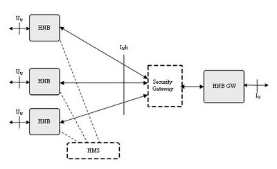
In 2008, Femto Forum was formed and it started discussion on the architecture. From 15 different proposals, consensus was reached in May over the Iuh interface as shown below.

There are two main standard development organizations (SDOs) shaping the standard for UMTS-related (UTRAN) femto technology: 3GPP and The Broadband Forum (BBF).
More about 3GPP here. BBF (http://www.broadbandforum.org) was called the DSL Forum until last year. As an SDO to meet the needs of fixed broadband technologies, it has created specifications mainly for DSL-related technologies. It consists of multiple Working Groups. The Broadband Home WG in particular is responsible for the specification of CPE device remote management. The specification is called CPE wide area network (WAN) Management Protocol (CWMP), which is commonly known by its document number, TR-069.

There are several other important organisations for femto technology. The two popular ones are the Femto Forum (www.femtoforum.org) and Next Generation Mobile Network (NGMN).

3GPP has different terminology for Femtocells and components related to that. They are as follows:

Generic term: Femtocell
3GPP Term: home NodeB (HNB)
Definition: The consumer premises equipment (CPE) device that functions as the small-scale nodeB by interfacing to the handset over the standard air interface (Uu) and connecting to the mobile network over the Iuh interface.

Generic term: FAP Gateway (FAP-GW) or Concentrator
3GPP Term: home NodeB gateway (HNB-GW)
Definition: The network element that directly terminates the Iuh interface with the HNB and the existing IuCS and IuPS interface with the CN. It effectively aggregates a large number of HNBs (i.e., Iuh interface) and presents it as a single IuCS/PS interface to the CN.

Generic term: Auto-Configuration Server (ACS)
3GPP Term: home NodeB management system (HMS)
Definition: The network element that terminates TR-069 with the HNB to handle the remote management of a large number of HNBs.

In addition, there is a security gateway (SeGW) that establishes IPsec tunnel to HNB. This ensures that all the Iuh traffic is securely protected from the devices in home to the HNB-GW.
The HNB-GW acts as a concentrator to aggregate a large number of HNBs which are logically represented as a single IuCS/IuPS interface to the CN. In other words, from the CN’s perspective, it appears as if it is connected to a single large radio network controller (RNC). This satisfies a key requirement from 3GPP system operators and many vendors that the femtocell system architecture not require any changes to existing CN systems.

The radio interface between HNB and UE is the standard RRC based air interface but has been modified to incude HNB specific changes like the closed subscriber group (CSG) related information.

Two new protocols were defined to address HNB-specific differences from the existing Iu interface protocol to 3GPP UMTS base stations (chiefly, RANAP at the application layer).

HNB Application Protocol (HNBAP): An application layer protocol that provides HNB-specific control features unique to HNB/femtocell deployment (e.g., registration of the HNB device with the HNBGW).

RANAP User Adaptation (RUA): Provides a lightweight adaptation function to allow RANAP messages and signaling information to be transported directly over Stream Control Transport Protocol (SCTP) rather than Iu, which uses a heavier and more complex protocol stack that is less well suited to femtocells operating over untrusted networks from home users (e.g., transported over DSL or cable modem connections).


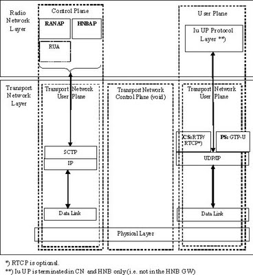
Figure above is representation of the protocol stack diagram being used in TS 25.467.

Security for femtocell networks consists of two major parts: femtocell (HNB) device authentication, and encryption/ciphering of bearer and control information across the untrusted Internet connection between the HNB and the HNB-GW (e.g., non-secure commercial Internet service). The 3GPP UMTS femtocell architecture provides solutions to both of these problems. 3GPP was not able to complete the standardization of security aspects in UMTS Release 8; however, the basic aspects of the architecture were agreed on, and were partially driven by broad industry support for a consensus security architecture facilitated in discussions within the Femto Forum. All security specifications will be completed in UMTS Release 9 (targeted for Dec. 2009).

FEMTOCELL MANAGEMENT

Management of femtocells is a very big topic and very important one for the reasons discussed above.

The BBF has created CWMP, also referred to as TR-069. TR-069 defines a generic framework to establish connection between the CPE and the automatic configuration server (ACS) to provide configuration of the CPE. The messages are defined in Simple Object Access Protocol (SOAP) methods based on XML encoding, transported over HTTP/TCP. It is flexible and extensive enough to incorporate various types of CPE devices using various technologies. In fact, although TR-069 was originally created to manage the DSL gateway device, it has been adopted by many other types of devices and technologies.

The fundamental functionalities TR-069 provides are as follows:
• Auto-configuration of the CPE and dynamic service provisioning
• Software/firmware management and upgrade
• Status and performance monitoring
• Diagnostics

The auto-configuration parameters are defined in a data model. Multiple data model specifications exist in the BBF in order to meet the needs of various CPE device types. In fact, the TR-069 data model is a family of documents that has grown over the years in order to meet the needs of supporting new types of CPE devices that emerge in the market. In this respect, femtocell is no exception. However, the two most common and generic data models are:
TR-098: “Internet Gateway Device Data Model for TR-069”
TR-106: “Data Model Template for TR-069-Enabled Devices”

HAND-IN AND FEMTO-TO-FEMTO HANDOVERS

The 3GPP specifications focused on handovers in only one direction initially — from femtocell devices to the macrocellular system (sometimes called handout). A conscious decision was made to exclude handover from the macrocellular system to the femtocell devices (sometimes called macro to femtocell hand-in). This decision was driven by two factors:
• There are a number of technical challenges in supporting hand-in with unmodified mobile devices and core network components.
• The system operator requirements clearly indicate that supporting handout is much more important to end users.
Nonetheless, there is still a strong desire to develop open, interoperable ways to support handin in an efficient and reliable manner, and the second phase of standards in 3GPP is anticipated to support such a capability.

NEXT-G EFFORTS

3GPP Release 8 defines the over-the-air radio signaling that is necessary to support LTE femtocells. However, there are a number of RAN transport and core network architecture, interface, and security aspects that will be addressed as part off 3GPP’s Release 9 work efforts. While it is preliminary as of the publication of this article, it seems highly likely that all necessary RAN transport and core network work efforts for LTE femtocells will be completed in 3GPP Release 9 (targeted for completion by the end of 2009).

3GPP STANDARDS ON FEMTOCELLS

[1] 3GPP TS 25.331: RRC
[2] 3GPP TS 25.367: Mobility Procedures for Home NodeB (HNB); Overall Description; Sage 2
[3] 3GPP TS 25.467: UTRAN Architecture for 3G Home NodeB; Stage 2
[4] 3GPP TS 25.469: UTRAN Iuh Interface Home NodeB (HNB) Application Part (HNBAP) Signaling
[5] 3GPP TS 25.468: UTRAN Iuh Interface RANAP User Adaption (RUA) Signaling
[6] 3GPP TR 3.020: Home (e)NodeB; Network Aspects -(http://www.3gpp.org/ftp/tsg_ran/WG3_Iu/R3_internal_TRs/R3.020_Home_eNodeB/)
[7] 3GPP TS 25.104: Base Station (BS) Radio Transmission and Reception (FDD)
[8] 3GPP TS 25.141: Base Station (BS) Conformance Testing (FDD)
[9] 3GPP TR 25.967: FDD Home NodeB RF Requirements
[10] 3GPP TS 22.011: Service Accessibility
[11] 3GPP TS 22.220: Service Requirements for Home NodeB (HNB) and Home eNodeB (HeNB)
[12] 3GPP TR 23.830: Architecture Aspects of Home NodeB and Home eNodeB
[13] 3GPP TR 23.832: IMS Aspects of Architecture for Home NodeB; Stage 2
[14] 3GPP TS 36.300: E-UTRA and E-UTRAN; Overall Description; Stage 2
[15] 3GPP TR 33.820: Security of H(e)NB 3GPP TR 32.821: Telecommunication Management; Study of Self-Organizing Networks (SON) Related OAM Interfaces for Home NodeB
[16] 3GPP TS 32.581: Telecommunications Management; Home Node B (HNB) Operations, Administration, Maintenance and Provisioning (OAM&P); Concepts and Requirements for Type 1 Interface HNB to HNB Management System (HMS)
[17] 3GPP TS 32.582: Telecommunications Management; Home NodeB (HNB) Operations, Administration, Maintenance and Provisioning (OAM&P); Information Model for Type 1 Interface HNB to HNB Management System (HMS)
[18] 3GPP TS 32.583: Telecommunications Management; Home NodeB (HNB) Operations, Administration, Maintenance and Provisioning (OAM&P); Procedure Flows for Type 1 Interface HNB to HNB Management System (HMS)
[19] 3GPP TS 32.584: Telecommunications Management; Home NodeB (HNB) Operations, Administration, Maintenance and Provisioning (OAM&P); XML Definitions for Type 1 Interface HNB to HNB Management System (HMS)
I would strongly recommend reading [3] and [6] for anyone who wants to gain better understanding of how Femtocells work.

My Headlines