Video Tutorial Atoll RF Planning
Atoll Import Tutorial Services
https://youtu.be/Zi7Gbxu4MGI
Atoll Tutorial Simulation
https://youtu.be/VnQimQGxKMY
Atoll Tutorial Set Traffic map
https://youtu.be/WgkLgE5lcvk
Atoll Tutorial Make Predictions based on Coverage
https://youtu.be/9dsOWVbCHTE
Atoll Tutorial Import Transmitters
https://youtu.be/I5xZ8eww_6M
Atoll Tutorial Import TMA Feeder & BTS Noise Figure
https://youtu.be/lXSq9HIQISA
Atoll Tutorial Import Sites
https://youtu.be/alzHCTHK5kI
Atoll Tutorial Import Environment
https://youtu.be/Z_Bing3mbv8
Atoll Tutorial Import Cells
https://youtu.be/s1D9dTw7Y9E
Atoll Tutorial Make Predictions based on Simulation
https://youtu.be/trrYYmY6oKA
Atoll Tutorial Draw Zones
https://youtu.be/lkQGQqQncC4
Tutorial Atoll for Chek RF Planning Result
https://youtu.be/gtP7obLqXYs
Tutorial Atoll Import User Profiles
https://youtu.be/q_9RjvJVYgMx
Atoll Tutorial Import Mobility Types
https://youtu.be/Z49aUmXmxIo
Tutorial Atoll Import Services
https://youtu.be/mwmQl6j1eyc
Tutorial Atoll Delete the Default Parameters
https://youtu.be/hruWLrzgz98
Senin, 29 Februari 2016
Minggu, 28 Februari 2016
LTE Non-Access-Stratum (NAS) Protocol
in NAS, Specification, LTE The non-access stratum (NAS) is highest stratum of the control plane between UE and MME at the radio interface. Main functions of the protocols that are part of the NAS are the support of mobility of the user equipment (UE) and the support of session management procedures to establish and maintain IP connectivity between the UE and a packet data network gateway (PDN GW).
NAS control protocol performs followings:
EPS bearer management;
Authentication;
ECM-IDLE mobility handling;
Paging origination in ECM-IDLE;
Security control.
Protocol specification
3GPP TS 24.301 - Non-Access-Stratum (NAS) protocol for Evolved Packet System (EPS); Stage 3
NAS control protocol performs followings:
EPS bearer management;
Authentication;
ECM-IDLE mobility handling;
Paging origination in ECM-IDLE;
Security control.
Protocol specification
3GPP TS 24.301 - Non-Access-Stratum (NAS) protocol for Evolved Packet System (EPS); Stage 3
LTE Stream Control Transmission Protocol (SCTP)
In computer networking,
the Stream Control Transmission Protocol
(SCTP) is a transport-layer
protocol
(protocol number 132[1]),
serving in a similar role to the popular protocols Transmission
Control Protocol (TCP) and User Datagram
Protocol (UDP). It provides some of the same
service features of both: it is message-oriented like UDP and ensures reliable,
in-sequence transport of messages with congestion control
like TCP.
The IETF
Signaling Transport (SIGTRAN)
working group defined the protocol in 2000,[2]
and the IETF Transport Area (TSVWG) working group maintains it. RFC 4960
defines the protocol. RFC 3286
provides an introduction.
Originally the SCTP was defined as a transport protocol for SS7 messages
to be transmitted over IP networks. As TCP and UDP it is seen as a
layer 4 transport protocol in the ISO OSI model.
The SCTP frames are called chunks. All chunks are associated to a
connection that guarantees in-order delivery. However, within the same
chunk there might be data blocks of different connections transmitted
simultaneously. In addition, it is also possible to send urgent packets
"out of order" with a higher priority.
SCTP also supports multihoming scenarios where one host owns multiple valid IP addresses.
Besides the data streams, SCTP frequently sends heartbeat messages to test the state of connection.
How SCTP works will be demonstrated by means of an example. Figure
1 shows the message flow required to transport the NAS signaling message
Attach Request from the eNB to MME across the S1 interface.

After setting up a RRC connection on the Uu interface between the UE and
the eNB, the UE sends the attach request message. When the appropriate
RRC transport container is received by the eNB, the establishment of a
dedicated SCTP stream on the S1 interface as shown in Figure 2 is
triggered.
The establishment of the SCTP stream starts with a SCTP initiation
message. It will always be sent by the eNB in the case of the attach
procedure, because the RRC connection is established earlier and the
request to transport the NAS message triggers the request to have a S1
connection. The SCTP initiation message contains the IP addresses of
both the eNB and MME. The individual subscriber for which this
connection is established is represented by a unique pair of SCTP source
port and destination port numbers.
The SCTP initiation needs to be acknowledged by the peer SCTP entity in
the MME. In the next step a SCTP cookie echo message is sent and
acknowledged by Cookie Echo ACK. In the protocol world, this is called a
heartbeat procedure. Such a procedure periodically checks the
availability and function of the active connection. Similar functions
with other message names are found, for example, in SS7 SCCP Inactivity
Test or GTP Echo Request/Response.
On SCTP higher layer messages are transported using SCTP datagram (SCTP
DTGR) packets. Each SCTP DTGR contains a Transaction Sequence Number
(TSN) in addition to source and destination address information. This
TSN will later be used by the peer entity to acknowledge the successful
reception of the DTGR by sending an SCTP selective ACK message on S1
that confirms error-free reception of the SCTP DTGR that carried the
attach request message. Further S1AP and NAS messages of this connection
will be transported in the same way and the Cookie Echo/Cookie Echo
ACKs will be sent periodically as long as the connection remains active.
If
the S1 signaling transport layer SCTP has problems in offering proper
functionality, there will be no signaling transport on S1 if the
problems are located in the eNB SCTP entity. If the MME suffers from
congestion or protocol errors on the SCTP level as shown in Figure 1.83,
the expected selective ACK messages will be missing (maybe not sent at
all, maybe sent with a TSN out of the expected range). This malfunction
may be detected by a NACK Cookie Echo and as a result the connection
will be terminated. Or the attach accept message expected to be received
by the UE will be missed. The missing attach accept message will be
recognized by the UE where a timer is guarding the NAS procedures. After
the guard timer expires on the UE side the attach request message will
be repeatedly sent up to n times (the counter value of n is configurable and typically signaled on the broadcast channel SIBs; the default value recommended by 3GPP is n =
5). If neither an attach request message nor an attach reject message
is received by the UE the handset will go back to IDLE when the maximum
number of attach request repetitions has been sent.

LTE Radio Resource Control (RRC)
Radio
Resource Control (RRC)
in Specification,
RRC,
LTE
RRC protocol layer exists in UE & eNodeb,
It is part of LTE air interface control
plane.
The main services and functions of the RRC sublayer
include:
Broadcast of System Information
related to the non-access stratum (NAS);
Broadcast of System Information
related to the access stratum (AS);
Paging;
Establishment, maintenance and
release of an RRC connection between the UE and E-UTRAN
Security functions including key
management;
Establishment, configuration,
maintenance and release of point to point Radio Bearers;
Mobility functions
QoS
management functions;
UE measurement reporting and
control of the reporting;
NAS direct message transfer to/from
NAS from/to UE.
LTE Medium Access Control (MAC)
MAC
protocol layer exists in UE & eNodeb,
It is part of LTE air interface control and user planes.
The main services and functions of
the MAC sublayer
include:
Mapping between logical channels
and transport channels;
Multiplexing/demultiplexing
of MAC SDUs belonging to one or different logical channels into/from transport
blocks (TB) delivered to/from the physical layer on transport channels;
scheduling information reporting;
Error correction through HARQ;
Priority handling between logical
channels of one UE;
Priority handling between UEs by
means of dynamic scheduling;
Transport format selection;
Padding.
Protocol
specification
3GPP TS 36.321
- Evolved Universal Terrestrial Radio Access (E-UTRA); Medium Access Control
(MAC) protocol specification
LTE RLC protocol
RLC
protocol layer
exists in UE & eNodeb, It is part of LTE air interface
control and user planes.
The main services and functions of
the RLC sublayer
include:
Transfer of upper layer PDUs;
Error
Correction through
ARQ (only for AM data transfer);
Concatenation, segmentation and reassembly of
RLC SDUs (only for UM and AM data transfer);
Re-segmentation of RLC data PDUs
(only for AM data transfer);
In sequence delivery of upper layer
PDUs (only for UM and AM data transfer);
Duplicate detection (only for UM
and AM data transfer);
Protocol error detection and
recovery;
RLC SDU discard (only for UM and AM
data transfer);
RLC re-establishment.
Protocol
specification
3GPP TS 36.322
- Evolved Universal Terrestrial Radio Access (E-UTRA); Radio Link Control (RLC)
protocol specification
LTE Packet Data Convergence Protocol (PDCP)
Packet
Data Convergence Protocol (PDCP)
in PDCP,
Specification,
LTE
PDCP protocol layer exists in UE & eNodeb,
It is part of LTE air interface control and user planes.
The main services and functions of
the PDCP sublayer
for the user plane include:
Header
compression and decompression: ROHC only;
Transfer
of user data;
In-sequence delivery of upper layer
PDUs at PDCP re-establishment procedure for RLC AM;
Duplicate detection of lower layer
SDUs at PDCP re-establishment procedure for RLC AM;
Retransmission of PDCP SDUs at
handover for RLC AM;
Ciphering and deciphering;
Timer-based SDU discard in uplink.
The main services and functions of
the PDCP for the control plane include:
Ciphering and Integrity Protection;
Transfer of control plane data.
Protocol
specification
3GPP TS 36.323
- Evolved Universal Terrestrial Radio Access (E-UTRA); Packet Data Convergence
Protocol (PDCP) specification
LTE Layers Data Flow
Below is a logical digram of E-UTRAN Protocol layers with a depiction of data flow through various layers:
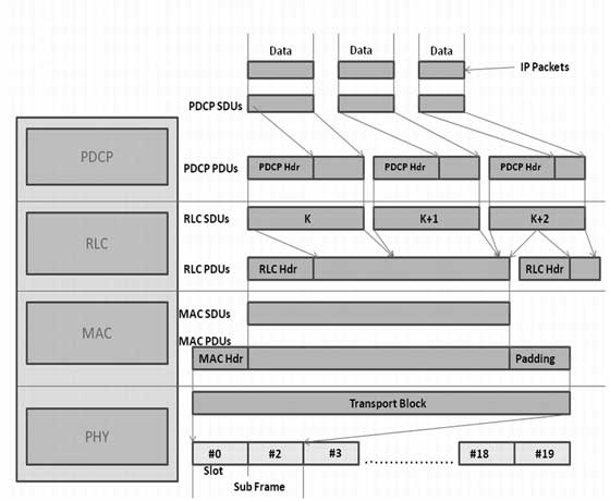
Packets received by a layer are called Service Data Unit (SDU) while the packet output of a layer is referred to by Protocol Data Unit (PDU). Let's see the flow of data from top to bottom:
Packets received by a layer are called Service Data Unit (SDU) while the packet output of a layer is referred to by Protocol Data Unit (PDU). Let's see the flow of data from top to bottom:
- IP Layer submits PDCP SDUs (IP Packets) to the PDCP layer. PDCP
layer does header compression and adds PDCP header to these PDCP SDUs.
PDCP Layer submits PDCP PDUs (RLC SDUs) to RLC layer.
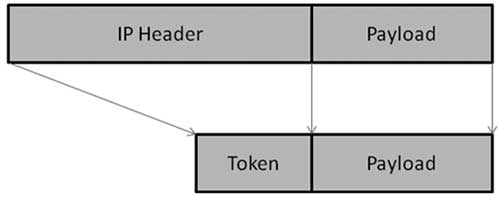
PDCP Header Compression : PDCP removes IP header (Minimum 20 bytes) from PDU, and adds Token of 1-4 bytes. Which provides a tremendous savings in the amount of header that would otherwise have to go over the air.
- RLC layer does segmentation of these SDUS to make the RLC PDUs.
RLC adds header based on RLC mode of operation. RLC submits these RLC
PDUs (MAC SDUs) to the MAC layer.
RLC Segmentation : If an RLC SDU is large, or the available radio data rate is low (resulting in small transport blocks), the RLC SDU may be split among several RLC PDUs. If the RLC SDU is small, or the available radio data rate is high, several RLC SDUs may be packed into a single PDU. - MAC layer adds header and does padding to fit this MAC SDU in TTI. MAC layer submits MAC PDU to physical layer for transmitting it onto physical channels.
- Physical channel transmits this data into slots of sub frame.
Sabtu, 27 Februari 2016
Dual carrier features results in IRAQ LTE-projects
Please, I would like to share the Dual carrier features results in IRAQ LTE-projects which includes :
1-LTE Inter-frequencyuencyCell Reselection
2-LTE Inter-frequencyuencyHandover
3-LTE Inter frequencyuencyLoad balancing
4-Load Based Idle Mode Mobility
AGENDAIntroduction
LTE Inter-frequencyuency
Cell Reselection
LTE Inter-frequencyuencyHandover
LTE Inter frequencyuency
Load balancing
Load Based
Idle Mode
MobilityConclusion
Link : http://adf.ly/1XY7ik
Jumat, 26 Februari 2016
Simulator Physical Resource Block or Resource Block (PRB or RB) in LTE
•Physical Resource Block or Resource Block (PRB or RB) --> 12 Sub carrier x 1 slot period in time domain
•Capacity allocation is based on RB
•Resource element (RE)
•1 sub carrier x 1 symbol period
•Theoretical minimum capacity in allocation unit
•1 RE is equivalent of 1 modulation symbol on a subcarrier, i.e. 2 bits for QPSK, 4 bits for 16QAM and 6 bits for 64 QAM
Use full link :
http://niviuk.free.fr/lte_ca_spectrum.php
http://dhagle.in/LTE
Jumat, 19 Februari 2016
4G LTE Interfaces, Gx(or S7) & Gxc Interfaces, Rx Interfaces , SGi Interfaces
Gxc
•Interface between Serving GW (S-GW) and PCRF (Policy and Charging Rule Function)
•This interface is only needed in case the S5/S8 interface is based on PMIP (IETF candidate)
•The reason is that only in this case the S-GW will perform the mapping between IP service flows in S5/S8 and GTP tunnels in the S1-U interface. The information to do the mapping comes from directly from the PCRF
Gx(Also referred as S7)
•Interface between PDN GW and PCRF (Policy and Charging Rule Function)
•It allows:
•the PCRF to request the setup of a SAE bearer with appropriate QoS
•the PDN GW to ask for the QoSof an SAE bearer to setup
•to indicate EPC status changes to the PCRF to apply a new policy rule.
Rx
•Interface between PCRF (Policy & Charging Rules Function) and the external PDN network/operators IMS (in general, towards the Service Domain)
•Standardized in 3GPP TS 29.214: “ Policy and Charging Control over the Rx reference point (release 8)”
SGi
•Interface used by the PDN GW to send and receive data to and from the external data network or Service Platform
•It is either IPv4 or IPv6 based
•Downlink data coming from the external PDN must be assigned to the right SAE bearer of the right user by analysis of the incoming packet’s IP addresses, port numbers, etc.
•This interface corresponds to the Giinterface in 2G/3G networks
•Standardized in 3GPP TS 29.061: “Interworking between the Public Land Mobile Network (PLMN) supporting packet based services and Packet Data Networks (PDN)
LTE Radio Interface , S10 & S6a Interfaces,S11 Interfaces, S5/S8 Interfaces
S10
•Interface between different MMEs
•Used during inter-MME tracking area updates (TAU) and handovers
•Inter-MME TAU: The new MME can contact the old MME the user had been registered before to retrieve data about identity (IMSI), security information (security context, authentication vectors) and active SAE bearers (PDN gateways to contact, QoS, etc.)
•Obviously S10 is a pure signaling interface, no user data runs on it.
S6a
•Interface between the MME and the HSS
•The MME uses it to retrieve subscription information from HSS (handover/tracking area restrictions, external PDN allowed, QoS, etc.) during attaches and updates
•The HSS can during these procedures also store the user’s current MME address in its database.
S11
•Interface between MME and a Serving GW
•A single MME can handle multiple Serving GW each one with its own S11 interface
•Used to coordinate the establishment of SAE bearers within the EPC
•SAE bearer setup can be started by the MME (default SAE bearer) or by the PDN Gateway.
S5/S8
•Interface between Serving GW and PDN GW
•S5: If Serving GW and PDN GW belong to the same network (non-roaming case)
•S8:If this is not the case (roaming case)
•S8 = S5 + inter-operator security functions
•Mainly used to transfer user packet data between PDN GW and Serving GW
•Signaling on S5/S8 is used to setup the associated bearer resources
•S5/S8 can be implemented either by reuse of the GTP protocol from 2G/3Gor by using Mobile IPv6 with some IETF enhancements.
LTE Radio Interface, X2 Interface ,S1-MME Interface, S1-U Interface
LTE-Uu
•Air interface of EUTRAN
•Based on OFDMA in downlink and SC-FDMA in uplink
•FDD and TDD duplex methods
•Scalable bandwidth: from 1.4 up to 20 MHz
•Data rates up to 100 Mbps(DL), 50Mbps (UL)
•MIMO (Multiple Input Multiple Output) is a major component although optional.
X2
•Inter eNB interface
•Handover coordination without involving the EPC
•X2AP: special signaling protocol
•During HO, Source eNB can use the X2 interface to forward downlink packets still buffered or arriving from the serving gateway to the target eNB.
•This will avoid loss of a huge amount of packets during inter-eNB handover.
S1-MME
•Control interface between eNB and MME
•MME and UE will exchange non-access stratum signaling via eNB through this interface.
•E.g.: if a UE performs a tracking area update the TRACKING AREA UPDATE REQUEST message will be sent from UE to eNB and the eNB will forward the message via S1-MME to the MME.
•S1AP:S1 Application Protocol
•S1flex -> 1 eNB to connect to several MME
S1-U
•User plane interface between eNB and serving gateway.
•It is a pure user data interface (U=User plane).
•S1flex-U also supported: a single eNB can connect to several Serving GWs.
•Which Serving GW a user’s SAE bearer will have to use is signaled from the MME of this user.
Selasa, 02 Februari 2016
Parakontel - Fastconn Collaboration 4G Training on RF Planning and Optimization from basic, advanced to expert level.
Each Training will be conduct during weekend (from 9am to 5pm).
13-14 Feb 2016 (2 Days)
## The Key Concepts of 4G LTE Drive test, Network Planning and Optimization ##
IDR 2Jt Normal (Early Bird: IDR 1.75Jt)
Early Bird Due Date: 07 Feb 2016
20-21 Feb 2016 (2 Days)
## Advanced 4G LTE RF Network Optimization ##
IDR 2.75Jt Normal (Early Bird: IDR 2.4Jt)
Early Bird Due Date: 08 Feb 2016
05-06 Mar 2016 (2 Days)
## 4G LTE RF Optimization Usecases (Expert Level) ##
IDR 3 Jt Normal (Early Bird: IDR 2.75Jt) -- For Local
IDR 3.5 Jt Normal (Early Bird: IDR 3.25Jt) -- For Expat
Early Bird Due Date: 10 Feb 2016
# Special Discount for COMPLETE Package #
Syllabus will be updated Soon...
Register Here: http://bit.ly/1OWZNXv
Langganan:
Postingan (Atom)
