| |
Successful assignments show the number of successful TCH allocations at call setup.
At unsuccessful assignment, the Assignment Complete message, sent by the MS, was never received by the BTS.
The formula is defined as:
% TCH ASSIGNMENT SUCCESS RATE | = | TFCASSALL | X 100 % |
|
| TASSATT |
|
|
Probable Reason | |
No dominant serving cell | The serving cell cannot cope with the TCH traffic. |
Severe congestion on TCH | Failing TCH allocation for assignment or handover due to congestion |
Low signal strength for call access | The signal strength might be higher on the BCCH than on the TCH. |
Interference | Disturbance on SDCCH or target TCH |
Faulty transceiver | Faulty equipment |
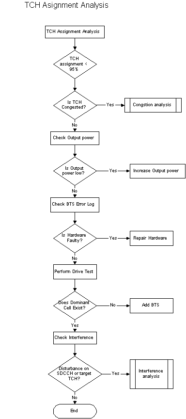
The following procedure should be performed for TCH Assignment analysis:
For TCH assignment success rate, the first thing, check the TCH Time Congestion.
If there is congestion on TCH, it is recommend doing the dimensioning and adding TRU based on carried TCH traffic demand.
If there is no congestion on TCH, check the output power of the BTS. If the output power is low, increase the output power.
If the output power is ok, check the faulty BTS by extracting BTS error log.
If hardware fault found, swap or repair HW.
Perform drivetests to check the coverage and received RxLEV.
If no dominant cell or similar signal strengths of a few cells found during drivetests, it is recommended to add BTS.
If there is no problem on the dominant cell, check the interference whether co-channel or adjacent channel.
Check the disturbance whether it is on SDCCH or target TCH. If disturbance found, improve the frequency plan.
Mostly, the problems of low TCH assignment are TCH availability and interference.
Traffic congestion is one of the major network problems in a mobile system. A high congestion deteriorates the overall performance of the network and should be minimized.
If the high traffic related to an occasional event, like sports event, fairs, conference, a temporary solution might be considered.
If there is a long-term growth the network capacity has to grow according to the demand.
The congestion analysis begins by identifying if there is only SDCCH or TCH congestion or both. Congestion on both SDCCH and TCH may mean that the only way to get rid of the congestion is to add more physical capacity in terms of transceivers or sites.
Consider how many channels that are allocated in the cell. If possible, expand the capacity with new transceivers, otherwise a new site must be implemented. Frequency planning schemes such as MRP and FLP could be used to relieve congestion. Microcells could be used to take traffic in severe congested areas.
In R8, the time congestion should be used instead of congestion based on access attempts as there is no way to estimate the number of access attempts a single mobile does.
Ericsson recommends using the SDCCH Time congestion as a KPI in R8. The formula is defined as:
SDCCH TIME CONGESTION OF TOTAL MEASUREMENT INTERVAL | = | CTCONGS | X 100 % |
|
| PERLEN * 60 |
|
|
where PERLEN is the measurement period in minutes.
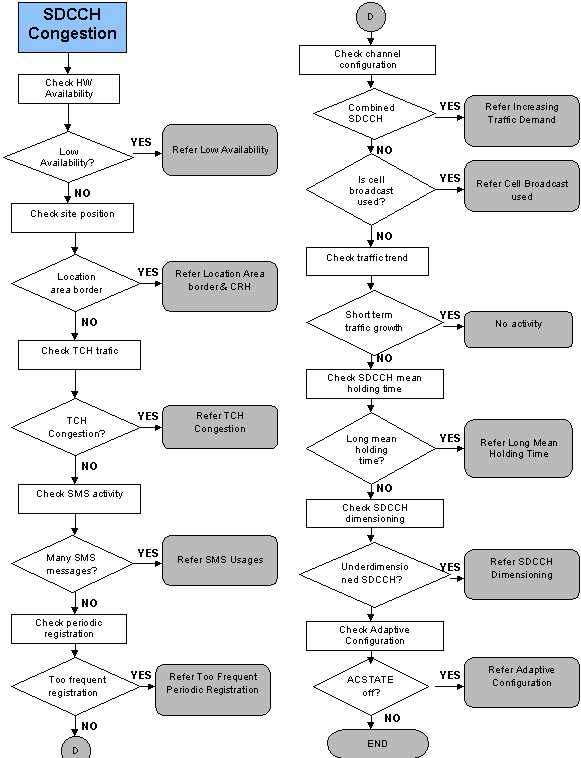
The flowchart below, Figure 51, explains a general approach to investigate SDCCH Congestion. The next section describes the action points in this flowchart. The reference to each action point is indicated on the flow chart as well.
What should I check?
Where do I look for it?
= | CAVAACC | X 100 % |
| |
| CAVASCAN * CNUCHCNT |
|
|
Why do I need to check this?
What should I check?
Where do I look for it?
Why do I need to check this?
What should I check?
Where do I look for it?
What should I check?
Where do I look for it?
TCH TIME CONGESTION OF TOTAL MEASUREMENT INTERVAL | = | TFTCONGS | X 100 % |
|
| PERLEN * 60 |
|
|
Why do I need to check this?
What should I check?
Where do I look for it?
Why do I need to check this?
What should I check?
Where do I look for it?
Why do I need to check this?
What should I check?
Where do I look for it?
Why do I need to check this?
What should I check?
Where do I look for it?
Why do I need to check this?
What should I check?
Where do I look for it?
SDCCH MEAN HOLDING TIME | = | CTRALACC*PERLEN*60 | X 100 % |
|
| CNSCAN*CMSESTAB |
|
|
Why do I need to check this?
What should I check?
Where do I look for it?
Why do I need to check this?
What should I check?
Where do I look for it?
Why do I need to check this?
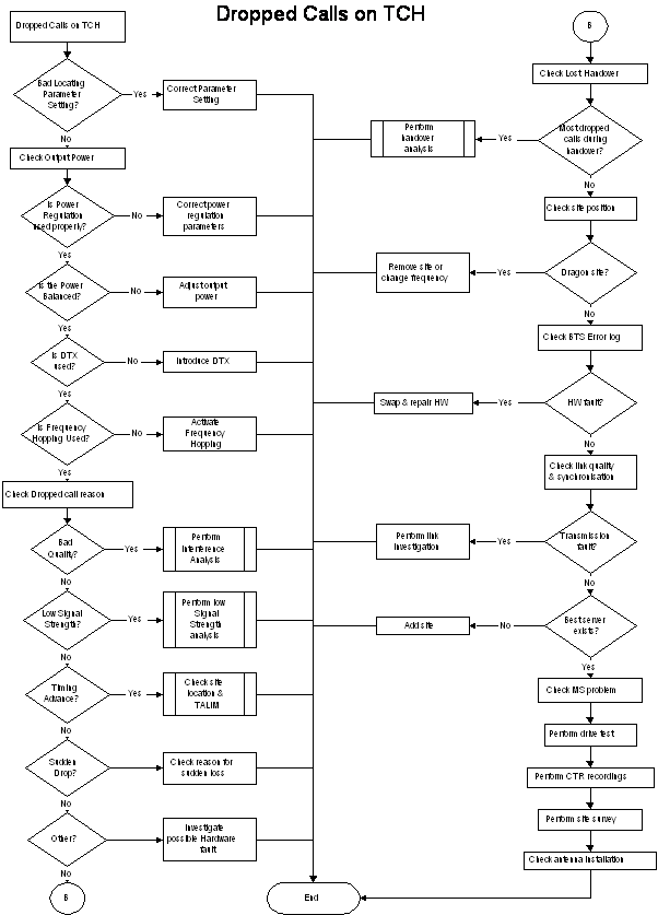
From technical perspective, dropped calls show the number of abnormal disconnection’s during call setup, SMS, supplementary service activation or during conversation. They are a few different counters for dropped calls, i.e. dropped calls due to low signal strength, bad quality, too high timing advance and miscellaneous is used to get an indication of the reason for possible bad performance.
From a subscriber point of view, dropped calls are those that interrupt an ongoing conversation, i.e. a call dropped on the TCH. If the call is dropped on the SDCCH the user simply re-dials again and hopefully succeeds with the new call setup. For this analysis we will focus on the drop call on the Traffic Channel (TCH).
TCH Drop call can be divided into a few categories:
1. Excessive Timing advance |
2. Low Signal Strength – UL/DL/BL |
3. BL Bad Quality – UL/DL/BL |
4. Sudden Loss |
5. Other reason (not standalone counter) |
Dropped connection due to failure is counted in counter TFNDROP, which step for the number of abnormally terminated connections. These counters are incremented when the BSC send ‘CLEAR REQUEST’ and when ‘CLEAR COMMAND’ message is received if the code differs from the cause codes ‘CALL CONTROL’ and ‘Handover successful’. If the ‘CLEAR REQUEST’ has been sent previously before ‘CLEAR COMMAND’, the counter will not step.
When a call is abnormally disconnected, that is ‘CLEAR REQUEST’ is sent to the MSC, a check is made in the function Assignment or Handover if any of the following urgency state existed. If more than one type of urgency state are indicated by the locating procedure, the following priority (highest priority first) is used to determine the type of urgency state:
1. Excessive Timing Advance (TA) |
2. Low signal strength in downlink and/or uplink |
3. Bad quality downlink and/or uplink |
4. Sudden loss of connection |
When type of urgency is determined, one of counters of this urgency state is stepped.
Probable Reason | |
Poor BSC Exchange Property setting | High LOWSSDL & LOWSSUL will give more drop reason due to SS and this might not show the actual drop. It is because drop due to SS is more priority than Quality. |
No dominant cell | Cell might be isolated or standalone. |
Antenna tilt & orientation | Too much downtilt sometimes might not cover a larger area and the subscriber might lose the SS. |
Output Power | Low output power might cause smaller border cell. |
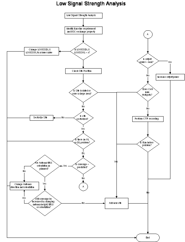
The following procedure should be performed for low signal strength analysis:
Identify the baseline requirement of design and BSC exchange property (setting for LOWSSUL/LOWSSDL).
Check the value for LOWSSDL & LOWSSUL. If it is higher than ACCMIN, change the parameter to a reasonable value since the drop reason will be more priority to SS compared to Quality.
Check the site position, antenna direction, position etc. This is to ensure the possible location is open to interference (open water environment) or isolated. Good map is needed for this.
Check if the site is sectorized or Omni. If it is Omni, set the cell into sectorized cell.
Check if the signal strength is uplink or downlink limited. Mostly, It is designed to be downlink limited.
Check the coverage cover expected area from the planet. If it is not, check the antenna tilt and orientation. Change the direction or tilt if it is too much downtilt or pointing to a wrong direction.
Sometime, low output power might cause low SS. Check output power and if it is low, increase the output power.
Check cell whether it has hotspots from drivetests. If found, adding new site is recommend.
In order to check power distribution, run Cell Traffic Recording (CTR) to that particular cell.
Check if the cell has indoor coverage problem. If yes, add micro site instead.
Internal
Co-channel or Adjacent channel interference causing internal interference. Possible problem of this is due to bad frequency plan, bad site location, congestion or too high antenna location.
External
Exists when there is another transmitter or something else acting as a transmitter outside the network such as TV transmission, CCTV, Wireless Cord Phone, AMPS network, repeaters or microwave links. To avoid the disturbance, the operator has to change affected frequencies or take action on the source of the disturbance.
Uplink Interference – Probable Reason | |
Poor MS Power regulation | MS at cell borders areas interfered by other mobiles on the co-channel or adjacent channel cell border as MS transmit in all directions. |
Bad frequency plan | Uplink interference might no be noticed by Automatic Frequency planning tool. The reason is that it is normally assumed that the radio link is reciprocal, the uplink is equal to the downlink. Sometime the case might be imbalance. |
No BTS Diversity | Lack of BTS diversity might loss 3-4 dB sensitivity. |
Faulty BTS receivers | Receiver sensitivity may be lower than specification. |
High Antenna position | Could cause co-channel sites overhead. |
Downlink Interference – Probable Reason | |
Poor BTS Power regulation | Non working BTS power regulation will increase the interference in co-channel cells. |
Bad frequency plan | Uplink interference might no be noticed by Automatic Frequency planning tool. The reason is that it is normally assumed that the radio link is reciprocal, the uplink is equal to the downlink. Sometime the case might be imbalance. |
Low BTS output power | Output power is less than intended. Co-channel interferers will be heard. |
Faulty BTS transmitter | Transmitter sensitivity may be lower than specification. |
Feeder problems | Water in feeders might cause disturbances. |
Environment | Open water might cause too large coverage area causing disturbance. |
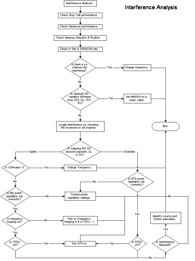
The following procedure should be performed for interference analysis:
Check the drop call performance for that particular cell. When the interference problem occurs in the cell, the drop call will be higher than usual. This might depends on the severity of the interference whether it is co-channel or adjacent channel.
Check the handover performance of the cell. The HO performance will also look bad especially when you look into the neighbor relation that has interference. For e.g. adjacent channel. (CNA consistency checking can detect this)
Check the antenna direction, position etc. This is to see whether the direction covers the right area, open space area (this can be seen by having good and updated map)
Check if the site is a dragon site. If the site is a dragon site, it might be possible to get interfered by co-channel from far away.
Check the co-channel sites, if found, change frequency and see the result. Mostly, changing the frequency will solve the interference problem.
Check the Intracell handover (normally for Intracell handover 25% Uplink and 75% Downlink) and if the variation is different from this. Intracell handover usually indicates bad quality and high signal strength. Too high number of intracell handover show a bad quality cell and if possible, you can reduce the number of intracell handover of MAXIHO to a smaller value based on the channel group.
Locate the interference from statistics based on MS reversion to old channel of total attempt. High number of reversion will show that the target frequency might be interfered.
Check the statistics from Outgoing Handover decision due to bad quality Uplink or Downlink from handover decision. High decision of handover due to quality will show the direction of interference.
Check if the interference is uplink interference (this might be an interference from other MSs) by analyze the ICM band for other band (not include band 1). If found on ICM > 3, change frequency.
Check the MS power regulation setting. If any poor setting found, correct the parameter. Improper setting of MS power regulation might cause interference. The feature used to reduce the MS power when the MS is near to the BTS and hoping that it might not interfere the uplink.
Check if the frequency hopping on or off. If more than 1 TRU, turn on the frequency hopping. Turning on the frequency will help to reduce interference by interference averaging.
Check if DTXU feature is on or off. If off, turn the DTX feature on. This will save the battery in the MS and reduce the interference.
If the interference is downlink (causing by other BTS interference), Check BTS power regulation. If any poor setting found, correct parameter setting.
Check if DTXD feature is on or off. If off, turn the DTX feature on. This is used to reduce interference and decrease BTS power consumption
If changing frequency or parameter cannot solve the interference for both uplink & downlink, it might be external interference.
Check antenna installation, ensure that the antenna is correctly installed
Check if another mobile network like AMPS is near to the location.
Check from the statistics if there is any pattern of bad quality reason. For example, for surveillance purpose, the CCTV or wireless alarm system might be turn on during nighttime only.
If external interference problem occurs, do drive test and report the usage of the frequency to authorities.
Drop call due to excessive TA happens when the TA value at drop call connection is higher than the cell parameter TALIM (TADROP > TALIM) and from this counter TFDISTA is incremented.
Probable Reason | |
Location | High sites or sites next to water pick up traffic from far away |
Parameter setting | Very low TALIM setting, which would indicate a ‘false’ excessive timing advance |
How to analyze:
Drop due other reason equal to total number of drops subtracts all drops with reason. If any of the above drop reason didn’t meet the criteria, the reason for drop will be in the ‘Other Reason’.
Probable Reason | |
H/W fault | Hardware Problem (Managed Object in BTS) |
Disturbance | Link/ Transmission disturbance problem |
Parameter Setting | Wrongly defined setting (for e.g. LAC – Location Area Code) |
Mobile Station | MS problem |
Interference | Interference problem (Uplink) |
How to analyze:
Sudden loss of connection is valid if none of the first three types of urgency state (excessive TA, low signal strength or bad quality) are indicated and also the locating procedure indicates missing measurement results from the MS.
The term Sudden Loss is used because if the network cannot establish a connection with the lost MS after a pre-defined period, the sudden loss counter is incremented if the last reported measurement from the MS does not fulfil any of the reasons mentioned above. Counter TFSUDLOS will step if the last measurement report missing in period of time.
Probable Reason | |
Environment | Very sudden and severe drop in signal strength, such as when subscriber enter into building, parking garages etc |
Interference | Very sudden and severe occurrence of interference or bad quality |
Battery or subscriber behavior | MS running out of battery during conversation or pulling out battery |
BTS H/W or MS fault | BTS Hardware fault & MS fault |
Transmission fault | Synchronization or ABIS link Fault |
How to analyze:
Handover is an important function, which shows the integrity of the GSM network. If the handover performance is poor, the subscriber will perceive the quality of the network as bad.
Probable Reason of Bad Handover Performance | |
Bad locating parameter settings | Bad setting might cause the locating will not rank the best cell as a candidate |
Uplink interference | Incoming handover failed as the target cell could not decode the handover burst message from the mobile |
Missing measurement frequency in BA-list | Prevent any handover to affected neighbor cells |
Extra measurement frequency | Can provide inaccuracy of measurement for handover decisions |
Co-Channel and Co-BSIC | Measurement result from neighbors can not be distinguished and MS may perform a handover to the wrong cell. |
Unnecessary neighbor relation | None or few handover might indicate a unsuitable neighbor relation. |
HW faults | Can cause bad neighbor relation. |
Permitted NCC (network color code) | Missing NCC of the neighbors will not allow any handover. |
Wrong use of HCS parameters | Cause unnecessary handover |
Congestion | High congestion might lead to dragged calls (handover performed at a not intended location) a lot of unsuccessful handover. |
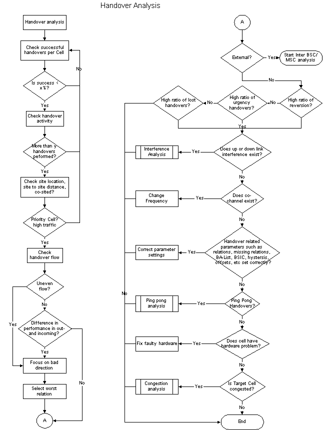
Handover Analysis Flowchart.
The following procedure should be performed for handover analysis:
- Check for the handover success rate below certain criteria for example X%. If it doesn’t meet the criteria and change the X% to a higher value and check for the next cell.
- Check the handover activity from the number of handover performed. If the number is above certain value for example Y and then take into consideration.
- Check the site location, whether the site to site distance or co-sited. (Good map is needed here).
- Check the handover flow whether is balance between incoming and outgoing.
- Check the difference performance of incoming and outgoing handover. This is to ensure the priority for more problem direction.
- Focus on the bad direction.
- Check the worst relation and pick one cell.
- Check the cell whether it is external or internal. If external, start inter-BSC analysis.
- If one of them is yes, check the uplink & downlink interference problem.
- Check the frequency plan. There might be problem on co-channel or adjacent channel.
- Check the handover related parameters such as relation, BA-list, BSIC, hysteresis, offsets etc.
- Check if assignment handover are used.
- Check if congested target cell. If the target cell is congested and then solve the congestion by adding TRU.
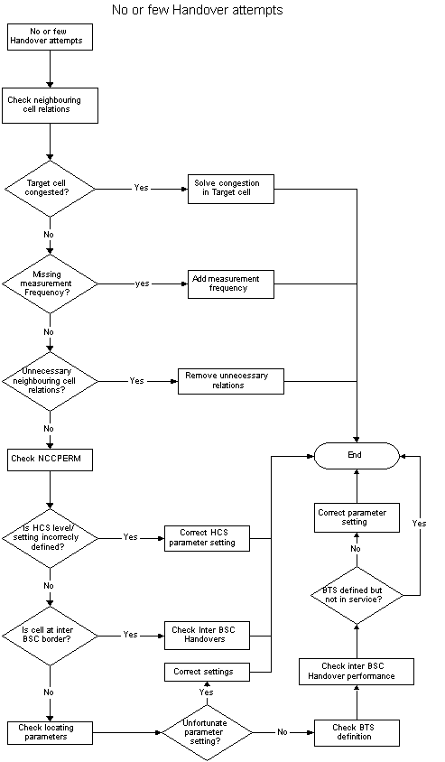
No or Few Handover Attempt Flowchart.
The following procedure should be performed for no or few handover attempts:
- Check from the unbalance relation whether the target cell is congested, if congested, solves the congestion problem.
- Check the missing measurement frequency (MBCCHNO) in Double BA-list in active list (if yes, add the measurement frequency in the BA-list.
- Check unnecessary neighbor cell relations and if found, remove unnecessary relations.
- Check the setting of the cells whether they are set in different layer of HCS. (Layer 1 is the highest priority)
- Check locating parameters and list out.
- Check BTS definition (RX commands especially RXMOP).
TEMS Investigation is an air interface test tool for real-time diagnostics. It lets you monitor voice channels as well as data transfer over GPRS, circuit-switched (CSD) or high-speed circuit-switched (HSCSD) connections. Data sessions can be conducted from within TEMS Investigation. TEMS Investigation is equipped with advanced testing and inspection functions as well as powerful analysis and post-processing features useful to the experienced RF engineer. Data is presented in real time throughout. This makes TEMS Investigation ideal for advanced drive testing sessions of troubleshooting, performance tuning, etc. All data can also be saved in logfiles for purposes of post-processing
Measurements in Drive Testing
* C/I---This is the carrier signal to interference (plus noise) ratio. It determines the quality and performance of the connection. The necessary threshold for good performance depends on the modulation type, the receiver design, and the service quality requirements (such as BER requirement)
* Rxlev---This is the received signal level, and is usually measured in dBm units. The Rxlev is measured on either
- The BCCH channel in idle mode
- Or on both the BCCH and the traffic channel, TCH
* BCCH : Broadcast Control Channel (provides general information about the network)
* TCH : Traffic Channel
Speech Quality---Speech quality can be evaluated by the following:
Subjective listening test
- A Personal opinion (okay, good enough, excellent, poor)
- MOS (mean opinion score (GSM standard procedure)
0: bad
1: poor
2: fair
3: good
4: excellen
* RxQual---This is a GSM standard metric, and is expressed in the range of 0 to 7 (0 meaning best quality). For descent speech quality, Rxlev should not exceed a value of 4 more than 5% of the time for non-hopping networks. For hopping networks, this is relaxed, and usually a threshold of 5 or 5.5 for the RxQual is used.
* SQI (Speech Quality Index)---This is not a GSM standard metric, and is only specific to the TEMS test equipments. It is expressed in the range of 0 to 30 dB (30 meaning best quality).
Limitations of drive testing
1. Drive testing can only test the network performance on the streets and roads where vehicles can go
2. It can not be used to assess network performance such as drop rates, and quality statistics for calls made from nearby houses, alleys (where cars can not go), and from nearby office buildings, and shopping plazas, and etc
3. For testing and collecting measurements in areas and places where the vehicles can not go, walk-in tests are required (indoor test).
TEMS Investigation GSM can be run in two different modes:
1. Drive testing mode. Information is read from one or several mobile stations, and optionally from a scanner and a GPS unit.
2. Analysis mode. Information is read from a logfile
| Title | Satellite Communication Engineering |
| Edition | |
| Call Number | |
| ISBN/ISSN | |
| Authors | K. J. Ray Liu |
| Medium | |
| Language | English |
| Publisher | Marcel Dekker, Inc. |
| Publish Year | 2002 |
| Publication Place | |
| Collation | |
| Abstract/Notes | Satellite communication is one of the most impressive spin-offs from space programs, and has made a major contribution to the pattern of international communications. The engineering aspect of satellite communications combines such diverse topics as antennas, radio wave propagation, signal processing, data communication, modulation, detection, coding, filtering, orbital mechanics, and electronics. Each is a major field of study and each has its own extensive literature. Satellite Communication Engineering emphasizes the relevant material from these areas that is important to the book�s subject matter and derives equations that the reader can follow and understand. The aim of this book is to present in a simple and concise manner the fundamental principles common to the majority of information communications systems. Mastering the basic principles permits moving on to concrete realizations without great difficulty. Throughout, concepts are developed mostly on an intuitive, physical basis, with further insight provided by Copyright © 2002 by Marcel Dekker, Inc. All Rights Reserved. means of a combination of applications and performance curves. Problem sets are provided for those seeking additional training. Starred sections containing basic mathematical development may be skipped with no loss of continuity by those seeking only a qualitative understanding. The book is intended for electrical, electronics, and communication engineering students, as well as practicing engineers wishing to familiarize themselves with the broad field of information transmission, particularly satellite communications. |
| Availability | There is no item/copy for this title yet |
| Location | There is no item/copy for this title yet |
| Image |  |
| File Attachment | View File |
| Back To Previous |
It is possible to analyze the system performance and trouble using above forward link analysis tool. It is important to check the logging mask according to the test objectives when collecting the data.
Reverse Link Test Tool and Equipments
Generally, SYSCAM is used to collect and monitor the reverse link data. Analyzing the SYSCAM Logging data, we can check the reverse FER, Measured Eb/No, Eb/No setpoint, FDCH/SCH Digital Gain.
| Tool/Equipments | Company | Main Functions |
| SYSCAM | Samsung | Collecting and monitoring the reverse link data for 1x |
| SCAT2000 | Samsung | Analyzing the logged data for 1x |
| SYSCAM_DO | Samsung | Collecting and monitoring the reverse link data for EVDO |
| SCAT2000_DO | Samsung | Analyzing the logged data for EVDO |
| Attenuator Box | - | Load reverse link by attenuating MS Tx pwr. |
| PC with LAN card | - | Test tool setup Interface between PC and System |
There are two types of test tool when performing the field test. It is composed of Forward Link Analysis tool and Reverse Link Analysis tool. The specification, manufacturer, quantity of each equipment will be provided in detail in separated document.
Forward Link test tool and equipment descriptions
Test tool and equipment are as follows when analyzing the data on the forward link.
| Tool/Equipments | Company | Main Functions |
| BlueRose | Will’ Tek | Mobile station monitoring and Data Logging tool on the forward link for 1x and EVDO. |
| IDA | Will’ Tek | Analyzing the logged data for 1x and EVDO. |
| Test Van | - | Test Tool setup and mobility |
| PC | - | Test Tool setup and Parameter change |
| Data cable | - | The interface cable between mobile and PC |
| Spectrum Analyzer | | BTS Transmit power measurement |
| Angle Detector compass | - | Antenna Installation Check |
