Di bawah ini adalah daftar beberapa terminologi dan singkatan yang digunakan dalam 5G NR. Tim kami terus memperbaruinya. Kunjungi secara teratur untuk menghubungi terminologi dan singkatan baru terkait 5G.
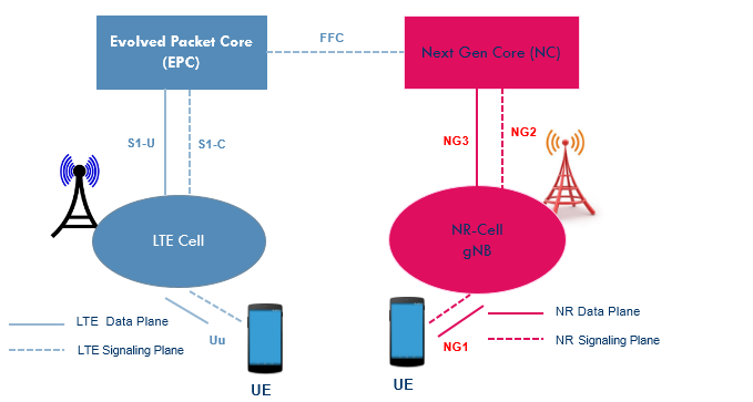
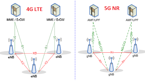
New RAN: Jaringan Akses Radio yang dapat mendukung NR / E-UTRA atau keduanya dan memiliki kemampuan untuk berinteraksi dengan Next Generation Core Network (NG-CN). NG-C / U adalah antarmuka Control / User Plane menuju NG-CN
gNB: BTS Radio Baru (NR) yang memiliki kemampuan untuk berinteraksi dengan 5G Core dinamakan sebagai NG-CN melalui antarmuka NG-C / U (NG2 / NG3) serta Core 4G yang dikenal sebagai Evolved Packet Core (EPC) melalui S1 Antarmuka -C / U.
eLTE eNB: eLTE eNB adalah eNodeB yang dikembangkan yang dapat mendukung konektivitas ke EPC dan juga NG-CN
Non-standalone NR: Ini adalah konfigurasi penyebaran Jaringan 5G, di mana gNB membutuhkan LTE eNodeB sebagai jangkar untuk konektivitas pesawat kontrol ke 4G EPC atau eLTE eNB sebagai jangkar untuk konektivitas pesawat kontrol ke NG-CN
Standalone NR: Ini adalah konfigurasi penyebaran Jaringan 5G di mana gNB tidak memerlukan bantuan untuk konektivitas ke Jaringan inti, ia dapat terhubung sendiri ke antarmuka NG-CN melalui NG2 dan NG3
E-UTRA Non-standalone: Ini adalah konfigurasi penyebaran Jaringan 5G di mana eLTE eNB membutuhkan gNB sebagai jangkar untuk konektivitas pesawat kontrol ke NG-CN.
Standalone E-UTRA: Ini adalah penyebaran jaringan 4G khas di mana 4G LTE eNB terhubung ke EPC
Xn Interface: Ini adalah antarmuka logis yang menghubungkan node RAN baru yaitu menghubungkan gNB ke gNB dan eLTE eNB ke gNB dan sebaliknya.
Baru-baru ini, 3GPP telah membekukan spesifikasi untuk 5G NR dan TS 38.104 bagian 5.2 memberikan daftar pita di mana NR (Radio Baru) dapat beroperasi. Sesuai rilis 3GPP 15, pita frekuensi ini desingated untuk rentang frekuensi yang berbeda (FR) dan spesifikasi saat ini (Rilis) mendefinisikannya sebagai FR1 dan FR2. Tabel di bawah ini menunjukkan rentang frekuensi yang sesuai untuk masing-masing FR. Penentuan Rentang Frekuensi Sesuai Rentang Frekuensi FR1 410 MHz - 7125 MHz FR2 24250 MHz - 52600 MHz
Klasifikasi Pita NR
Terlepas dari FR (rentang frekuensi) pita NR dapat diklasifikasikan ke dalam tiga kategori
Frequency Division Duplex Bands (FDD) Band Dupleks Divisi Waktu (TDD) Pita Pelengkap (SUL): Pita Suplemen Downlink & Pita Suplemen Uplink
NR telah memperkenalkan notasi baru untuk band yang dimulai dengan "n" mis. Band 20 dicatat sebagai n20 di mana dalam LTE disebut sebagai B20.
Anda dapat melihat iklan dari penyedia seluler Anda menggembar-gemborkan kedatangan 5G, dan Anda bertanya-tanya apa itu dan apa yang membuatnya berbeda dari versi teknologi seluler sebelumnya.
Dalam artikel ini, kami melihat zaman baru dalam timeline seluler dan bagaimana hal itu dapat menguntungkan bisnis Anda.
Apa itu 5G?
5G adalah teknologi nirkabel baru yang dirancang untuk memberikan kecepatan yang lebih cepat dan waktu latensi yang lebih baik daripada sistem sel generasi sebelumnya. Sebagai perbandingan, 5G dikatakan memasok kecepatan unduhan hingga 20 Gbps, sedangkan teknologi LTE (4G) saat ini mengunduh pada 50 Mbps. Namun, yang lebih penting daripada kecepatan adalah waktu laten 5G. Dengan teknologi LTE saat ini, latensi (atau waktu yang dibutuhkan sinyal untuk terhubung ke jaringan) adalah sekitar 40 milidetik. 5G menyala sekitar 1 milidetik.
Sebagai contoh mengapa latensi sangat penting, pikirkan kapan saja Anda menonton siaran berita langsung di mana satu jangkar berada di Amerika Serikat, dan lainnya berada di negara lain. Perhatikan berapa lama kadang-kadang diperlukan satu orang untuk merespons yang lain; ini karena waktu latensi yang rendah.
Siapa yang Mengembangkan 5G
Semua operator signifikan di Amerika Serikat: Verizon, AT&T, T-Mobile, dan Sprint sedang mengembangkan dan menggunakan jaringan 5G. Namun, jaringan ini masih baru dalam tahap awal dan baru diluncurkan di kota-kota besar. Ini akan menjadi tahun sebelum 5G adalah standar di seluruh negeri.
Bagaimana 5G Dapat Mendapat Manfaat Bisnis
Banyak perusahaan menikmati tenaga kerja yang dikerahkan di seluruh dunia, yang mengandalkan koneksi berkecepatan tinggi untuk berkomunikasi dan berkolaborasi. Karena lebih banyak orang bekerja dari rumah, 5G membuat komunikasi yang lebih cepat dan lebih dapat diandalkan. Sebagai sebuah bisnis, Anda dapat mengurangi kebutuhan akan karyawan 'di tempat' dan memanfaatkan pekerja dengan lebih baik seperti pekerja lepas atau pekerja kontrak yang menghemat uang Anda, sambil meningkatkan efektivitas dan keahlian tenaga kerja Anda.
Hal lain yang perlu dipertimbangkan ketika melakukan lompatan ke 5G adalah faktor layanan pelanggan. Koneksi data yang lebih cepat dan lebih andal membuat melayani pelanggan Anda lebih mudah dan memberikan pengalaman yang lebih baik bagi mereka, yang meningkatkan loyalitas pelanggan.
Selain itu, komunikasi yang lebih cepat dan jaringan yang lebih andal memungkinkan bisnis Anda menjadi lebih efisien. Ketika komunikasi antara orang-orang dan mesin atau mesin ke perangkat terjadi dengan lebih sedikit cegukan dan lebih sedikit downtime karena masalah jaringan, perusahaan Anda beroperasi lebih lancar dan efisien, menghemat uang dan meningkatkan efisiensi.
Keselamatan adalah bidang lain yang perlu dipertimbangkan ketika berbicara tentang data berkecepatan tinggi dan jaringan yang lebih andal yang diberikan 5G. Pertimbangkan kemajuan kendaraan yang bisa mengemudi sendiri dan teknologi lain yang mengandalkan sistem untuk membuat orang tetap aman. Sebagai sebuah perusahaan, menggunakan mesin dengan kemampuan untuk berbicara satu sama lain secara real time menghadirkan dunia kemungkinan untuk menjaga pekerja dan pelanggan tetap aman dan meningkatkan operasi bisnis Anda secara keseluruhan.
Sementara 5G secara nasional masih jauh, bisnis yang mempersiapkannya sekarang akan berada di depan permainan begitu tiba.
Artikel diajukan oleh Mark D. Hearn (CEO dan Presiden di Network Control)
Tentang Mark D. Hearn Sebagai CEO dan Presiden, Mark D. Hearn memimpin visi dan arah Kontrol Jaringan. Dia telah menjadi pelayan aktif di pasar manajemen telekomunikasi sejak 1987 dan diakui sebagai pelopor dalam industri TEM, setelah memulai salah satu perusahaan TEM pertama yang berbasis perangkat lunak.
3GPP masih dalam proses menyelesaikan Indikator Kinerja Utama (KPI) 5G / NR.KPI ini didorong dari ITM-2020 dan beberapa di antaranya tercantum di bawah ini.KPI ini terutama mempertimbangkan tiga kategori besar: Enhanced Mobile Broadband (eMBB) Mission Critical Control (MCC) Massive Internet of Things (Massive IoT)
Kualitas sinyal yang ditransmisikan menentukan seberapa besar sinyal yang ditransmisikan menyimpang dari sinyal ideal dalam hal domain frekuensi, domain timer atau properti modulasi. Kerusakan pada sinyal yang ditransmisikan diperkenalkan oleh bagian radio pemancar yang memiliki sifat nonlinear, mis.
Dalam spesifikasinya, kualitas sinyal dapat dinilai untuk Base Station atau Mobile Terminal dengan mengukur berikut ini
Kesalahan Frekuensi (Fe) Kualitas Modulasi (EVM) Time Alignment Error (TAE)
Dalam posting ini kita akan membahas untuk Time Alignment Error.
Time Alignment Error (TAE)
NR Base station mentransmisikan sinyal dari dua atau lebih antena mis. keragaman pemancar dan MIMO. Untuk agregasi pembawa, pembawa juga dapat ditransmisikan dari antena yang berbeda. Agar perangkat seluler dapat menerima dan mendekodekan sinyal dari beberapa antena dengan benar, diperlukan bingkai sinyal yang harus sejajar dengan rentang yang ditentukan.
Hubungan Frame Timing antara dua cabang pemancar ditentukan dalam hal kesalahan penyelarasan waktu maksimum antara cabang pemancar. Kesalahan maksimum yang diizinkan tergantung pada fitur atau kombinasi fitur di cabang-cabang pemancar, mis. Transmit Diveristy, MIMO, Carrier Aggress, dll. Tujuannya untuk mengukur kesalahan ini untuk menemukan penundaan antara sinyal dari dua Antena yang dipancarkan.
Rangka sinyal NR yang ada di konektor antena pemancar BS atau konektor TAB tidak sepenuhnya selaras dengan waktu. Sinyal RF yang ada pada konektor antena pemancar BS atau batas array transceiver dapat mengalami perbedaan waktu tertentu dalam hubungannya satu sama lain.
TAE ditentukan untuk serangkaian sinyal / konfigurasi pemancar / mode transmisi.
Untuk BS tipe 1-C, TAE didefinisikan sebagai perbedaan waktu terbesar antara dua sinyal yang dimiliki oleh konektor antena yang berbeda untuk set sinyal / konfigurasi pemancar / mode transmisi tertentu. Untuk BS tipe 1-H, TAE didefinisikan sebagai perbedaan waktu terbesar antara dua sinyal milik TAB konektor milik grup pemancar berbeda di batas array transceiver, di mana grup pemancar terkait dengan konektor TAB dalam array unit transceiver yang sesuai dengan keanekaragaman TX, transmisi MIMO, agregasi pembawa untuk sekumpulan sinyal tertentu / konfigurasi pemancar / mode transmisi / mode transmisi.
Persyaratan Minimum TAE untuk BS tipe 1-C dan 1-H
Transmisi keragaman MIMO atau TX pada setiap frekuensi pembawa, TAE tidak boleh melebihi 65 ns Dalam hal CA bersebelahan intra-band, dengan atau tanpa keragaman MIMO atau TX, TAE tidak boleh melebihi 260ns Intra-band non-contiguous CA, dengan atau tanpa keragaman MIMO atau TX, TAE tidak boleh melebihi 3μs. CA antar-band, dengan atau tanpa keragaman MIMO atau TX, TAE tidak boleh melebihi 3μs.
Link Budget adalah penghitungan untung dan rugi total dalam sistem untuk menyimpulkan tingkat sinyal yang diterima (RxSL) di penerima (UE). Level sinyal yang diterima kemudian dibandingkan dengan sensitivitas penerima (RxS) untuk memeriksa apakah status saluran lulus atau gagal.
Status saluran adalah "Lulus" jika tingkat sinyal yang diterima (RxSL) lebih baik daripada sensitivitas penerimaan (RxS), selain itu "Gagal". Di bawah ini adalah gambar yang menunjukkan beberapa nilai contoh untuk menggambarkan berbagai parameter input yang digunakan untuk penghitungan Link Budget:
Rumus berikut digunakan untuk menghitung anggaran sinyal yang diterima (RxSL) tautan 5G:
Level Sinyal yang Diterima pada penerima (dBm) = gNodeB daya pancar (dBm) - 10 * log10 (kuantitas subcarrier) + penguatan antena GNodeB (dBi) - Kehilangan kabel gNodeB (dB) - Kehilangan jalur (dB) - Kehilangan jalur (dB) - Kehilangan penetrasi (dB) - kehilangan dedaunan (dB) - kehilangan blok tubuh (dB) - margin interferensi (dB) - margin hujan / es (dB) - margin fading lambat (dB) - kehilangan blok tubuh (dB) - gain antena UE (dB) + gain antena UE (dB) ……… ………… (1)
Dalam contoh gambar di atas, nilai yang dihitung RxSL adalah 77 dBm dan sensitivitas penerimaan (RxS) adalah -93 dan status tautannya adalah "Lulus". Biasanya tautan pembatas adalah tautan naik dan disarankan untuk menghitung Link Budget tautan bawah dan tautan tautan secara terpisah dan kemudian mempertimbangkan tautan terburuk.
Untuk menghitung path loss, kita perlu menggunakan model propagasi yang sesuai untuk 5G (5G menggunakan model propagasi 3D yang didefinisikan dalam 3GPP 36.873. Model UMa, UMi, dan RMa berlaku untuk pita frekuensi 2–6 GHz dan kemudian diperluas hingga 0,5– 100 GHz dalam 3GPP 38.901).
Sebagai contoh dan jika kita mempertimbangkan model UMa untuk kasus Line Of Sight (LOS), rumus path loss diberikan sebagai berikut:
Jelas dari rumus di atas dan untuk menghitung path loss, kami memerlukan informasi "d" yang merupakan jarak antara pemancar dan penerima (jari-jari sel) dan frekuensi pusat (fc). Jika jari-jari sel sesuai dengan rentang sel maks, maka kehilangan jalur akan sesuai dengan kehilangan jalur maksimum yang diizinkan (MAPL).
Setelah kita mengetahui nilai path loss, maka dimungkinkan untuk menghitung level sinyal yang diterima yang akan dibandingkan dengan sensitivitas penerima
Sensitivitas penerima, bergantung pada Thermal noise power (dBm), noise figure (dB), ambang demodulasi SINR (dB). Sensitivitas penerima dihitung menggunakan rumus di bawah ini:
Kebisingan termal dihitung menggunakan rumus berikut: K * T * BW di mana "K" adalah konstanta Boltzmann dan "T" adalah suhu di Kelvin dan "BW" adalah bandwidth.
Noise Figure dan SINR adalah nilai-nilai spesifik vendor yang bergantung terutama pada kinerja perangkat keras dan kinerja decoding Skema Modulasi.
Anda dapat menerapkan persamaan (1) menjadi excel dan memvariasikan jari-jari sel sampai tingkat sinyal penerimaan lebih baik atau sama dengan sensitivitas penerima.
Jika Anda ingin menyimpulkan secara langsung apa yang akan menjadi jari-jari sel yang sesuai dengan sensitivitas penerimaan tertentu, kita dapat menggunakan rumus Link Budget (1) dan mengganti Level Sinyal yang Diterima pada penerima (dBm) dengan sensitivitas penerimaan.
Kami menyimpulkan jari-jari sel "d" dari rumus (5) dan itu diberikan dengan rumus di bawah ini:
Jarak (d) = 10 Daya ((PL-28-20 * Log10 (fc)) / 22) ……………… .. (7)
Contoh jika path loss sama dengan 78,4 dB, maka radius Cell adalah 120m!
Melihat kembali rumus path loss (5), kami menyimpulkan bahwa faktor utama yang mengontrol nilai path loss adalah ambang demodulasi SINR (dB) yang berarti untuk nilai SINR yang lebih tinggi (modulasi yang lebih baik), path loss lebih rendah dan oleh karena itu Cell radius lebih kecil! … Diperlukan lebih banyak stasiun basis 5G.
Reference Signal Power = Max Tx Power - 10 x log 10 (RBcell x 12) (dBm)
Contoh dengan Max Tx Power 40 dBm, maka jika : Sub-carrier Spacing 15 KHz 270 RBs with 50MHz Reference Signal Power = 40 – 10 x log10(270 x 12) = 40 – 35.10 Reference Signal Power = 4.9 dBm
Sub-carrier Spacing 30 KHz 273 RBs with 100MHz Reference Signal Power = 40 – 10 x log10(273 x 12) = 40 – 35.15 Reference Signal Power = 4.85 dBm
Sub-carrier Spacing 60 KHz 130 RBs with 100MHz Reference Signal Power = 40 – 10 x log10(130 x 12) = 40 – 31.93 Reference Signal Power = 8.07 dBm
Dan untuk Total Transmit Power = Max Tx Power + 10 x log 10 (No. of Tx Antenna) (dBm) Contoh : Total Transmit Power with 8 Tx Antenna = 40 + 10 x log10 (8) = 40 + 9.03 =49.03 dBm Total Transmit Power with 16 Tx Antenna = 40 + 10 x log10 (16) = 40 + 12.04 =52.04 dBm Total Transmit Power with 64 Tx Antenna = 40 + 10 x log10 (64) = 40 + 18.06 =58.06 dBm Total Transmit Power with 128 Tx Antenna = 40 + 10 x log10 (128) = 40 + 21.07 =61.07 dBm
NR is
a major new radio access technology developed by 3GPP, as a logical further
step beyond LTE-Advanced Pro. But like LTE, NR uses modulation based on OFDM
for both downlink and uplink
4G LTE Dimensioning Essentials Coverage, Capacity and Baseband
Existing WCDMA/HSPA 2.1 GHz grids can be reused for LTE deployment at 2.1 GHz Existing WCDMA/HSPA 2.1 GHz grids can be reused for LTE deployment at 2.6 GHz Existing GSM 1.8 GHz can be reused for LTE deployment at 2.1 GHz LTE Voice provides same coverage as GSM Voice but offers much higher spectrum efficiency (#simultaneous users) (tbd) LTE Voice provides same coverage as HSPA Voice LTE TDD loses ~2..3dB compared to FDD due to sharing resources in time Beamforming does not bring significant coverage gain however results in capacity boost (tbd) LTE deployment at Digital Dividend band provides extreme coverage and makes difference for PRACH planning Typical LTE Link Budget depending on the feature set is about 160..165dB maximum allowable path loss usually limited by uplink coverage Baseband is not likely to be a limiting factor in LTE dimensioning Control channels are not likely to limit LTE coverage Spectral Efficiency depends on many factors & assumptions LTE DL Spectral Efficiency is ~1.8 bps/Hz (3..4 times reference HSPA Release 6) LTE UL Spectral Efficiency is ~0.7 bps/Hz (2..3 times reference HSPA Release 6) LTE 6-sector site solution reduces the number of coverage sites by ~35% LTE 6-sector site solution brings ~80% site throughput gain compared to 3-sector LTE dimensioning & planning tools provide consistent path from simple link budget and capacity estimation to topology-aware network evaluation
How to make LTE Link Budget more aggressive within reasonable range of changes? How to make LTE Capacity more aggressive within reasonable range of changes? (tbd)
What are the
mobile operator plans to deploy OpenRAN in their 4G and, eventually, in
their 5G networks? In this survey of mobile operators that we did for
Mavenir, these were the key findings:
- All surveyed operators are considering using OpenRAN in their networks
- 43% of respondents are open to replace current vendors when deploying OpenRAN
- Cost savings were mentioned by 25% of respondents as a reason to consider multiple vendors
- 84% operators will consider deploying RRUs and BBUs from different vendors in OpenRAN deployments
- Lower cost radios are a key component to OpenRAN adoption Link : https://senzafili.com/wp-content/uploads/2019/10/SenzaFili_MavenirSurveyRed.pdf
Fungsi-fungsi enode B : The eNB hosts the following functions: •
Functions for Radio Resource Management: Radio Bearer Control, Radio
Admission Control, Connection Mobility Control, Dynamic allocation of
resources to UEs in both uplink and downlink (scheduling); • IP header compression and encryption of user data stream; • Selection of an MME at UE attachment when no routing to an MME can be determined from the information provided by the UE; • Routing of User Plane data towards Serving Gateway; • Scheduling and transmission of paging messages (originated from the MME); • Scheduling and transmission of broadcast information (originated from the MME or O&M
Version 2.0 of NYUSIM, the open source 5G & 6G channel model simulator software, is now available to download
Version 2.0 Changes
Three important channel modeling
components, spatial consistency, human blockage, and outdoor-to-indoor
(O2I) penetration loss, are implemented in NYUSIM 2.0. Each modeling
component will be introduced as follows.
Spatial Consistency:
Spatial consistency indicates continuous and realistic channel
evolution along the user terminal (UT) trajectory in a local area.
NYUSIM with spatial consistency simulates spatially correlated channel
impulse responses when a UT moves in a local area or multiple UTs are
closely spaced.
Human Blockage Shadowing Loss:
NYUSIM 2.0 can simulate human blockage shadowing loss due to a person
near the mobile phone (UT) who may block the transmission link. mmWave
links are more susceptible to blockage effects because of the short
wavelength and the usage of large antenna arrays. The shadowing caused
by humans and vehicles has to be taken into account for link budget
analysis.
O2I Penetration Loss:
NYUSIM 2.0 can simulate the channel responses with building penetration
loss for the UTs inside the building. O2I penetration loss becomes more
prominent at mmWave frequencies. Many modern buildings are constructed
with concrete and have infrared reflecting (IRR) glass, which induce a
large penetration loss when a mmWave signal is transmitted from outdoor
to indoor or vice versa.
Berikut adalah urutan cek Optimization untuk performance Retainability pada 3G : Hardware Transmission External Interference Crossfeeder Co Scrambling code Coverage Problem Neighbouring Problem Problem in 2G network Database Parameter Problem
contoh yang masuk dalam kategori Retainability adalah CCSR (call
completion success rate) CS Voice, CCSR CS Video, CCSR PS, dan HSDPA
Retainability Success Rate
As 5G New Radio (NR) moves into development, enabling technologies
such as multiple input, multiple output (MIMO) and beamforming are
critical. But these technologies can pose challenges to designers who
need to implement them in 5G base stations and devices.
You’ll use active phased
array antennas to implement MIMO and beamforming in base stations and
devices. While these active antennas help overcome signal propagation
issues, offer flexibility, and improve the performance of 5G
communications, they also create test challenges. These include
accommodating for greater mmWave frequency path loss, verifying RF
performance of 3D antenna beam patterns over-the-air (OTA), and
optimizing base station performance under real-world conditions.
As 5G New Radio (NR) networks ramp up, you’ll need to do live
network testing to ensure beams transmit accurately and to achieve
throughput per cell, throughput per device, and Quality of Experience
(QoE) metrics.
But did you know that
changes in radio access with beam-based cells will change test
methodologies and require both scanning receivers and test UEs for field
verification? 5G NR deployments are mostly in new frequency ranges –
3.5 GHz and 28 to 29 GHz – which means changes in radio access
techniques and network architecture.
As 5G New Radio (NR) moves into development, enabling technologies
such as multiple input, multiple output (MIMO) and beamforming are
critical. But these technologies can pose challenges to designers who
need to implement them in 5G base stations and devices.
You’ll use active phased
array antennas to implement MIMO and beamforming in base stations and
devices. While these active antennas help overcome signal propagation
issues, offer flexibility, and improve the performance of 5G
communications, they also create test challenges. These include
accommodating for greater mmWave frequency path loss, verifying RF
performance of 3D antenna beam patterns over-the-air (OTA), and
optimizing base station performance under real-world conditions.
ask : Mengapa setiap enodeB membutuhkan license yang berbeda-beda? ans : karena setiap enodeB mempunyai unique fingerpoint dan setiap unique fingerpoint mempunyai unique backplane number.
SMO adalah Software Management Organizer,salah satu fungsinya untuk upgrade software, membuat license, backup semua site.
Cara meningkatkan KPI HOSR di suatu cluster: 1. cari attempt HO dari cell source ke cell target yg jumlahnya banyak misalnya lebih dari 100x attempt 2. dari situ filter lagi yang HOSRnya lebih besar dari 99% 3.
kemudian lihat relasi antar cellnya, dan buatlah agar lebih mudah
handover ke cell tersebut dengan memainkan parameter CIO (cell
individual offset) dan kunci nilainya (jangan keubah secara otomatis
oleh SON) 4. dari CIO yang diubah tsb,coba buat t311nya sedikit lebih lama untuk jaga-jaga biar gak drop. Dikit aja jangan terlalu lama.
Udah
gitu aja, jika anda benar melakukannya maka nilai HOSR di cluster tsb
bisa naik significant. Yang perlu diperhatikan dari teknik di atas
adalah, anda harus dapat update terakhir nilai current CIOnya terlebih
dahulu, lalu eksekusi secara cepat di waktu yang sama.
Dengan cara di atas prinsipnya adalah HO attempt yang banyak dan nilainya baik (>99%) jumlahnya diperbanyak lagi.
Sebaliknya cari yang HO antar cellnya buruk, misal <50 attemptnya="" banyak="" dan="" ho.="" lalu="" p="" persulitlah="" untuk="">
my note for t311 dan t301 : Timer t311 dan t301 itu berjalan sendiri-sendiri, tidak bisa bersamaan. Jadi gini ceritanya....
Jika
UE deteksi HO failure, RLF, dll maka butuh re-establish kan ya, nah
jika butuh re-establish maka harus dapat cell lain yang suitable
sehingga timer t311 dimulai. Dalam pencariannya, jika t311 belum expire
namun sudah menemukan cell lain yang suitable tsb, maka RRC
Reestablishment procedure diproses sehingga t311 stop dan t301 dimulai.
Sharing sore how to improve LTE SSR (Setup Success Rate), Hal-hal yang perlu dilakukan : - cek kontributor site yang RRCnya bermasalah - cek dari site itu alarmnya ada atau tidak - cek status due to PUCCH rejection - cek maxnumactUE, maxnumrrc,dll Bila tidak ada masalah, maka reset site.
Share how to improve ERAB Drop : - cek status dropnya due to apa? misal UE lostkah, eutran generated kah, TNL kah, RNL kah - cek parameter setting site apa sudah benar seperti n310, n311, t310, t311 - cek fitur DRX aktif gak, jika aktif cek apakah sudah max settingan DRXnya - lihat RET settingnya sudah make sense belum - cek A3offset bila kaitannya dengan handover
HO preparation failed, penyebab yang mungkin terjadi : - enode B target belum terregister di MME - enode B punya lebih dari 1 TAC (TAC conflict) - settingan a2/a3 threshold kurang tepat - Interupt by TAU - source MME, target MME, target SGW ada yang bermasalah.
RTWP (receive total wideband power) dapat anda gunakan sebagai
pendeteksi interference. Jika dalam 1 site terdiri dari 3 sektor, dan
hanya 1 sektor yg nilai RTWP nya tinggi sedangkan lainnya rendah maka
ada kemungkinan masalah hardware yg harus anda periksa.
Namun
jika RTWP pada suatu area cukup tinggi, maka ada kemungkinan terjadi
external interference yg harus ditemukan sumbernya. Bisa berupa repeater
yg mengganggu yg sedang bekerja pada frekuensi yg sama atau berdekatan
5G researchers and R&D designers face
critical challenges when it comes to physical layer modeling and
simulation. Issues exist across the entire communication chain,
including baseband, RF/antenna, and channel model simulation. Learn a
cross-domain, model-based simulation approach to evaluate throughput
performance of the mmWave channel, and beamforming array antenna with
hardware impairments and reference baseband models that support the 3GPP
NR standard.
Three Key Learnings:
Learn how a 5G system architect should think about simulation.
Understand the basics of system modeling and simulation.
See a real-world example of a mmWave channel and beamforming array antenna
Stand a chance to win an eGift cardif you answer the quiz correctly during the session.
If you cannot attend the live event, please register and we will send you the recording.
Sincerely,
Keysight Technologies
Physical Layer Modeling Principles of 5G New Radio
Aug 20, 2019
10:30 a.m. SGT
The
interactive Ookla 5G Map tracks 5G rollouts in cities across the globe.
Updated weekly from verified public sources and Ookla data, you can
follow operators' newest 5G networks on @Ookla5GMap.
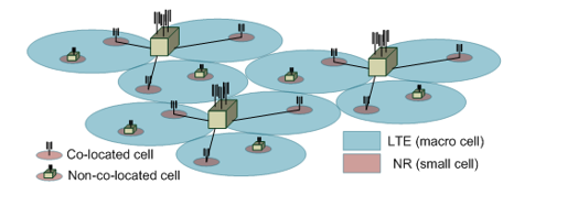
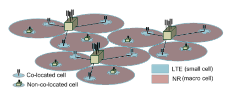
NR is capable of working in Non-standalone as well as standalone
deployments, the Phase 1 deployment is to be considered as
Non-standalone deployments. In terms of cell layout, A 5G NR cell can be
deployed in both homogeneous and heterogeneous deployments and be
following three cases can be considered.
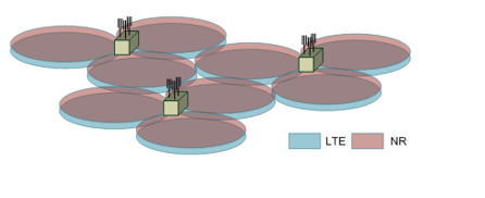
Case #1 Homogeneous deployment where LTE cell and
NR cells provide the similar coverage, this will happen when NR is
operating in the same band as LTE is operating. In this deployment,
cells are co-located cells
Case #2 Heterogeneous deployment where LTE and NR
cells are a different size. In this kind of deployment LTE cell is large
cell size to meet coverage requirement while NR cell size is small to
meet the capacity requirements. Here the NR cell can be deployed as a
co-located cell or a non-located cell as a hot spot.
Case#3 Heterogeneous deployment where LTE and NR
cells are a different size. In this kind of deployment NR cell is large
cell size to meet coverage requirement while LTE cell size is small to
meet the capacity requirements. Here the NR cell can be deployed as a
co-located cell or a non-located cell as a hot spot.
4G LTE and 5G NR Radio Network Architecture
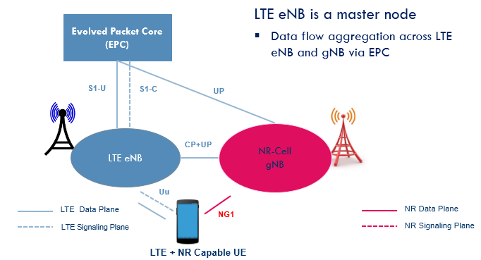
The deployment scenarios in terms of Core Network-RAN connection can be the following: LTE eNB is a master node
This network topology is going to be
most famous for the Phase 1 non-standalone deployments. LTE eNB will be
master and anchor the NR cell. All the signaling procedure shall be done
at LTE cell.
gNB is a master node
This network deployment shall be part of
phase 2 where NR cell shall have stand-alone operational capabilities
and it shall capable of anchoring the eLTE eNB. All signaling procedure
shall be done at NR cell.
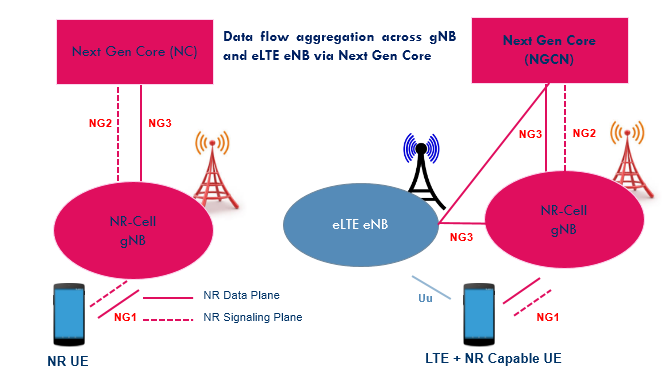
eLTE eNB is a master node
An eLTE eNB shall have capabilities to
communicate the Next Gen Core network. A release 14/release 15 LTE cell
can be considered as eLTE eNB. Here eLTE cell can be deployed standalone
with Next Gen Core or eLTE eNB connected with Next Gen Core anchoring a
non-stand alone NR cell.
Individual RAT with Inter Mobility
In this network topology, both LTE and
NR Radio access network are connected to their respective Core network
to operated in a standalone environment and supporting mobility for LTE
to NR cell and visa verse.
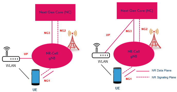
Inter-working with WLAN
In phase 2 , when NR is capable to work
as a standalone cell , it can be further enhanced to inter work with
WLAN for Wi-Fi offloading and to utilize the benefits of the unpaid
spectrum.
The Reference Signal Power and the total transmit power of the cell
can calculated by using a single channel power using following formula,
Maximum Transmit Power indicates the transmit power in dBm per single channel
Reference Signal Power is the power in dBm per RE of single channel
RBcell indicate total RB number based on the cell bandwidth each RB with 12REs
Example Calculation
Consider a system is configured with Max Transmit Power as 40 dBm (10
watt per channel) and calculation can be done with different
sub-carrier spacing Sub-carrier Spacing 15 KHz 270 RBs with 50MHz
Reference Signal Power = 40 – 10 x log10(270 x 12) = 40 – 35.10
Reference Signal Power = 4.9 dBm
Sub-carrier Spacing 30 KHz 273 RBs with 100MHz
Reference Signal Power = 40 – 10 x log10(273 x 12) = 40 – 35.15
Reference Signal Power = 4.85 dBm
Sub-carrier Spacing 60 KHz 130 RBs with 100MHz
Reference Signal Power = 40 – 10 x log10(130 x 12) = 40 – 31.93
Reference Signal Power = 8.07 dBm
If you not able to co-related the carrier spacing with RB count please read our older post 5G New Radio Throughput Calculation embedded PDF page 6 or NR Resource Block Definition and RBs Calculation
The total transmit power of NR base station can be calculated taking
Max Transmit power and No. of Tx antenna into account with following
formula.
Consider same 40 Bm as cell Max power, the total Tx power can be
calculated for different antenna configurations e.g. 8 antenna , 16
antenna, 64 antenna and 128 antenna systems.
Total Transmit Power with 8 Tx Antenna = 40 + 10 x log10 (8) = 40 + 9.03 =49.03 dBm
Total Transmit Power with 16 Tx Antenna = 40 + 10 x log10 (16) = 40 + 12.04 =52.04 dBm
Total Transmit Power with 64 Tx Antenna = 40 + 10 x log10 (64) = 40 + 18.06 =58.06 dBm
Total Transmit Power with 128 Tx Antenna = 40 + 10 x log10 (128) = 40 + 21.07 =61.07 dBm
Join
Keysight World 2019 to increase your technical expertise and become a
master in your field. The next best thing to attend in person is
watching from the comfort of your desk. We will broadcast Keysight World
Singapore live. All tracks. All day.
Tune
in to the experts at Keysight World as they discuss how advances in
technology are enabling the evolution of 5G and autonomous vehicles.
Discover how to securely manage the network needed to handle massive
amounts of real-time data generated by new applications.
Dive deep into a technical track:
5G-
Gain insight into 5G NR Standards, explore data throughput and
over-the-air challenges, and learn about 5G's impact towards drive test
and simulation requirement.
Automotive & Energy - Ensure your designs for autonomous vehicles, advanced power systems, radar, and V2X are brought to market safely and securely.
Data Center & Telecom - Hear the latest on data center networking and computing standards (PCIe® 5.0, DDR5), and solutions for 400G and beyond.
Network Operations & Security - Explore the shift from cloud to edge computing and see how to mitigate operational and security issues.
Invite your friends:
Spread
the innovation thoughts to a friend or colleague by simply referring
them to participate in live broadcast and stand a chance to receive an eGift card! Refer to live broadcast registration form for more details.
I am currently looking for a number of 2G, 3G and LTE NPO Lead Engineers to work 6 month extendable contracts based in Kenya.
Requirements: - Experience working on 2G/3G/LTE - Experience working on Huawei and ZTE - Planning and optimization experience - Nokia experience is a plus
Along with 5G comes revolutionary changes
to your 5G core (5GC). Proceed with confidence by testing these network
functions in isolation and from end-to-end.
*DOWNLOAD GRATIS e-BOOK "SMART CITY: Konsep, Model, & Teknologi -
Bunga Rampai Pengetahuan, Gagasan, & Rekomendasi ITS untuk
Indonesia"*. Buku Pertama di Indonesia yang membahas sekaligus
menyajikan Studi Kasus SMART CITY scr komprehensif mencakup *6 Dimensi*
Smart City rekomendasi Kemenkominfo (Smart Governance, Smart Branding,
Smart Living, Smart Economy, Smart Environment, & Smart Society).
Berisi *46 tulisan* dari *81 Peneliti Smart City Lintas Disiplin 25
Departemen ITS*. Diendorse oleh *8 Pemimpin Daerah* di Indonesia
Diterbitkan oleh Association for Information Systems - Indonesia chapter
(AISINDO).
*Download e-Book GRATIS* di: http://aisindo.org/aisindo-store/store/
------------------------------------
Bismillaahirrohmaanirrohiim,
mohon bantuan memforward ke forum-forum pemerintah, masyarakat,
praktisi, akademisi & pihak2 lain pemangku kepentingan Smart City di
Indonesia & di kota/kabupaten/provinsi anda. Semoga tulisan-tulisan
di buku ini mampu sedikit banyak membuka wawasan, memunculkan ide,
& memotivasi Pemimpin Daerah, Kementrian, Pelaksana Lapangan,
Praktisi, & Peneliti utk terus membuat Inovasi-Inovasi Kebaikan utk
kota/kab/provinsi di seluruh Indonesia.
*Download e-Book GRATIS*: http://aisindo.org/aisindo-store/store/
---------------------------------
_*Buku
fisik* berukuran B5, 696 halaman, berat 1,4 kg, sampul hardcover. Jika
anda tertarik membeli dan memiliki *Buku Fisik* Smart City ini silahkan
WA staf layanan AISINDO di *08123037371* dan dapat *Discount 40%* mjd
hanya Rp 150ribu (dr harga standar Rp 250rb) + ongkos kirim._
--------------------------------
Mohon
bantuan di Broadcast ke forum-forum/group Bapak/Ibu, pimpinan-pimpinan,
rekan Bapak/Ibu. Semoga bermanfaat dicatat Alloh sbg amal kebaikan
& kontribusi kebaikan & perbaikan Indonesia kita, aamiin.
As 5G becomes a reality, mobile operators are facing new engineering challenges to deploy 5G NR networks.
During
this webinar, we will be presenting how Atoll can help plan 5G NR
networks using key 5G NR technical features, through several examples
and use cases:
Coverage footprint for different frequency bands (mmWave, sub-6GHz)
Using different frame configurations
Beamforming configuration impact on coverage
Massive MIMO capacity gains
Simulating 5G NR performance using 3D traffic
As usual, a Q&A session will follow presentations and demonstrations. Sign up now!
(Please use your corporate email address)
May 23, 2019 9am (Paris)/3am (New-York)/3pm (Hong Kong) 5pm (Paris)/11am (New-York)/11pm (Hong Kong)
May 28, 2019 9am (Paris)/3am (New-York)/3pm (Hong Kong) 5pm (Paris)/11am (New-York)/11pm (Hong Kong)
Join
Keysight's Engineering Education webinars for electronic design and
test insights. For your continuous learning with Keysight, we have added
the following webinars to our 5G series:
Physical Layer Modelling Principles of 5G New Radio April 24, 2019, 11:00am CET
5G researchers and
R&D designers face critical challenges when it comes to physical
layer modelling and simulation. Issues exist across the entire
communication chain, including baseband, RF/antenna and channel model
simulation.
Learn a cross-domain, model-based simulation approach to evaluate
throughput performance of the mmWave channel and beamforming array
antenna with hardware impairments and reference baseband models that
support the 3GPP NR standard.
Redefining Drive Test for 5G May 16, 2019, 11:00am CET
5G NR deployments will include massive MIMO and beamforming, which
requires a different type of drive test coverage measurements and
Quality of Experience (QoE) assessments.
Learn about 5G NR field measurement and drive test that can be used to optimise 5G QoE in both FR1 and FR2.
If you cannot attend the live events, register anyway and we will send you the recordings.
Mobile
World Congress has come and gone for another year and GSA has added
great deal of information to the GAMBoD database, which is the source of
all our reports – the vast majority of which are free to download.
5G continues to be a strong industry focus and you will find reports on 5G networks, technology and spectrum on the GSA Website. 5G Security is a hot topic and GSA has just produced a 5G Security Primer white paper that considers the security improvements 5G will bring to mobile networks.
GSA has launched the industry’s first 5G Device Ecosystem database - part of the GAMBoD service – and published the first 5G Device Ecosystem report.
We have identified 33 5G devices from 27 suppliers and will be updating
the database every month. If you are a device vendor then please inform
us of new 5G devices you are launching at research@gsacom.com and we will add them to the database.

 gNB is a master node