Kamis, 29 April 2010

TRX Check

Purpose : to verify damage TRX in each sector

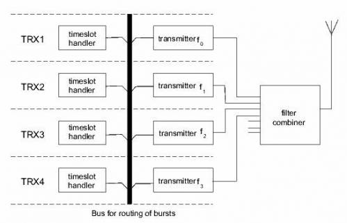
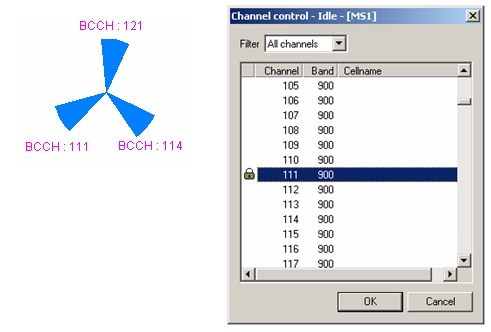
Where is TRX ?

trx-whatis

1. Lock BCCH ARFCN certain sector : Click Toolbar Lock on Channel trx-lockicon (ie. Check TRX Sector 1, Lock BCCH 111)

trx-lock

2. Disable Handover : Click Toolbar Disable Handover trx-dishoicon

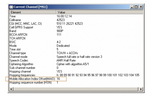
3. See MAIO on Current Channel window

trx-curch

Time Slot Check

Purpose : Check Time Slot in each TCH (if Freq Hop : NO or Base Band)

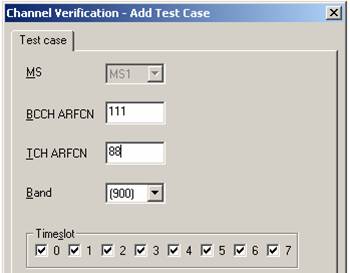
1. Setup Channel Verification : Menu Bar Control -> GSM Channel Verification

ts-setch

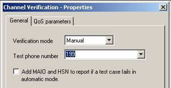
2. Setup test phone number : Click Properties on Channel Verification window ts-propicon

ts-dial

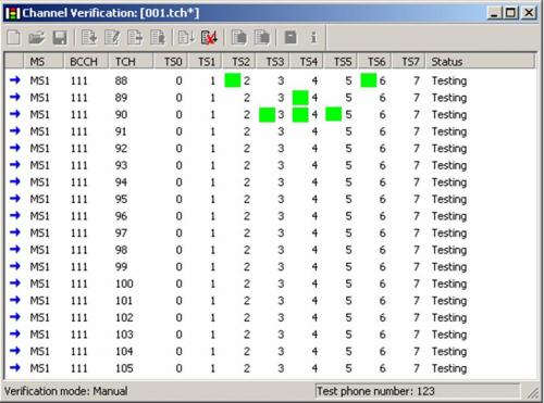
3. Green mark means time slot have been used

ts-tested

2G Frequency Scanning

Purpose : to verify level signal each BCCH ARFCN plan

1. Setup frequency scan : Click Scan Properties 2Gscan-scanicon

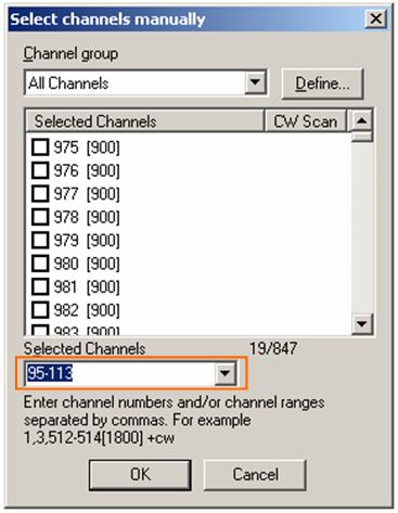
2. Select channels : Tab Scanned channels -> Manual selection -> Select

3. Setup Selected Channels (ie. BCCH ARFCN are 95-113)

2Gscan-selchan

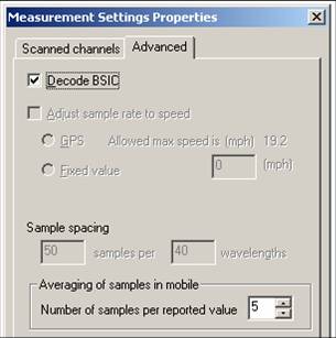
4. Decode BSIC

2Gscan-decbsic

5. Start Scanning : Click toolbar Start Scanning 2Gscan-start

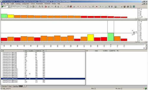
6. See Scanner Bar Chart Window : Menu Bar Presentation -> GSM -> Frequency Scanner -> Scanner Bar Chart

2Gscan-scbarchrt

MapInfo (Plot IEs)

Before post process in mapinfo, created *.tab file from logfile in TEMS :

1. Export logfile : Menu Bar Logfile -> Export Logfile

2. Click Add Order mapinfo-addicon

3. Choose Format : MapInfo Tab-file

4. Setup IEs (Info Elements)

for GSM Dedicated or Idle :

- RxLev Full (dBm)

- RxLev Sub (dBm)

- RxQual Full

- RxQual Sub

- SQI

- TA

- Cell Id

- Frequncy Band

- Latitude

- Longitude

for WCDMA Dedicated / Idle / Scanner :

- AS Cell Name

- AS CPICH Ec/No

- AS CPICH RSCP

- SAN CPICH Ec/No

- SAN CPICH RSCP

- SAN Cell Id (CI Part)

- Sc 1st Aggr Ec (dBm) -> Scanner

- Sc 1st Aggr EcIo (dB) -> Scanner

- Sc Best SC -> Scanner

- Latitude

- Longitude

5. Configure Options Tab
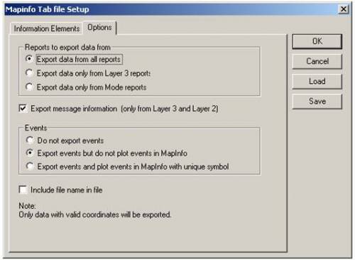
mapinfo-option

6. Save *.mex

7. Choose Logfile : Click Browse file

8. If there are more than one logfile we can merge it by Merge Output

9. Choose Output directory : Click Browse dir

10. Give Prefix : Ded if Dedicated and Idle if Idle
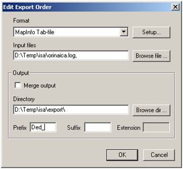
mapinfo-prefix

11. Start process, click start mapinfo-starticon

mapinfo-export

12. If done, status Success

13. There were created four files for each action (*.dat, *.id, *.map, *.tab)
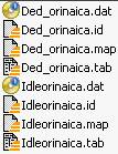
mapinfo-createdfiles

14. Open the exported file into MapInfo : Menu Tab File -> Open
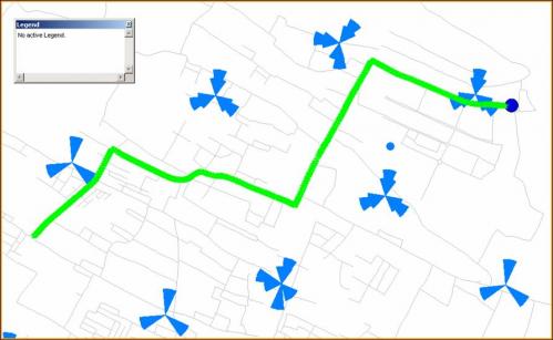
mapinfo-openexport

15. Create Thematic Map : Menu Tab Map -> Create Thematic Map

16. Choose Type -> Range

17. Template Name -> Region Ranges
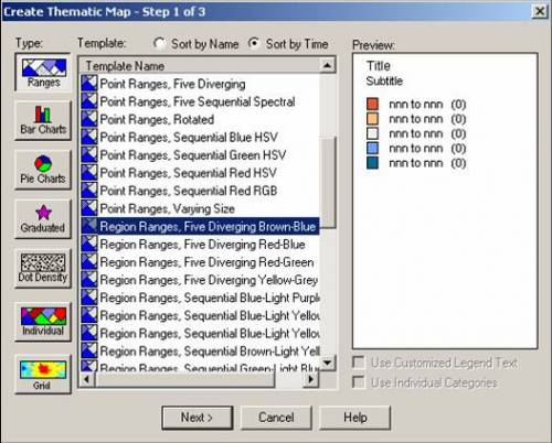
mapinfo-thematic

18. Choose Table and Field (ie. Plotting RXQUAL_SUB from Dedicated mode)

mapinfo-seltable

19. Customize Ranges, Style and Legend.
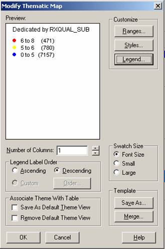
mapinfo-index

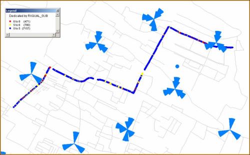
20. Example Dedicated by RXQUAL_SUB

mapinfo-result

EVENTS on RXQUAL_SUB

21. Create Events on RXQUAL_SUB

22. Open again the exported file (Ded_orinaica)

23. Create Thematic Map : Menu Tab Map -> Create Thematic Map

24. Choose Type -> Individual

25. Template Name -> Region IndValue Default

26. Choose Table and Field
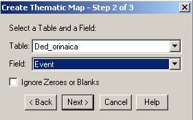
mapinfo-event

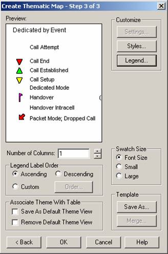
27. Customize Style and Legend

mapinfo-eventindex

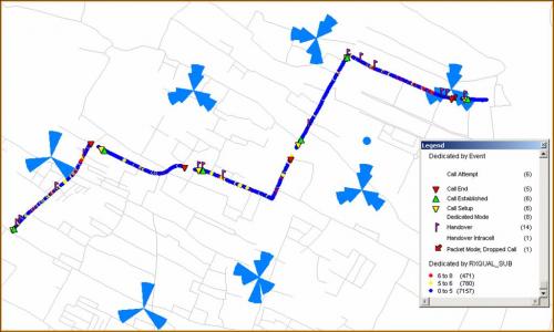
28. Example Events on RXQUAL_SUB

mapinfo-resultevent

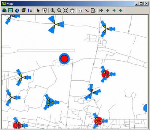
SPIDER GRAPH

29. Activate spider graph : Menu Tab Tools -> Tool Manager

30. Spider Graph Load and Autoload

31. See table structure of cell in MCOM Site : Menu Tab Table -> Maintenance -> Table Structure -> View/Modify Table choose MCOM Site
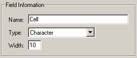
mapinfo-spdgrph01

32. See table structure of CI in exported file : Manu Tab Table -> Maintenance -> Table Structure -> View/Modify Table choose exported file (ie. Ded_orinaica) -> Change type structure of CI

mapinfo-spdgrph02

33. Click OK

34. Create Spider Graph : Tools -> Spider Graph -> Spider Graph

35. Choose Origin and Destination table
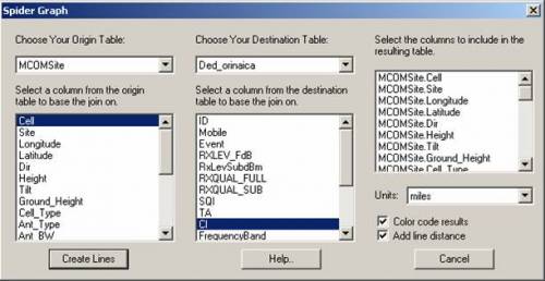
mapinfo-oridest

36. Save the Spider Graph table : Save Copy As -> (ie. orinaica)

37. From Spider Graph, We can analyze :

- Dominant Cells

- Overshoot Cells

- Swap Feeder
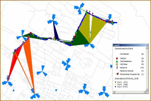
mapinfo-resultspider


Drive Test Report Generator

1. Open TEMS Data Collection : Start -> TEMS Products -> TEMS Investigations6.1.4 Data Collection

2. Menu Tab Logfile -> Report Generator

3. Add logfile

repgen-add

4. Setup Output directory

repgen-outdir

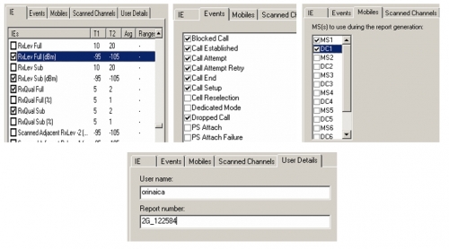
5. Setup Report properties

6. Setup IEs, Events, Mobiles, and User Details

repgen-setup

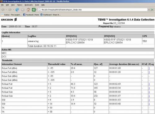
7. Result of Report Generator in *.htm

repgen-result


Go Drive Test

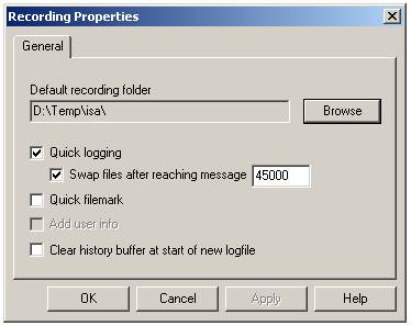
1. Configure Recording Properties : Menu Tab Logfile -> Recording Properties

2. Select recording folder : Click Browse -> Select Directory

3. Select Quick logging and setup size of swap file “after reaching message “

godt-recprop

4. Use 2G or 3G configured workspace (with spacific map : road, route, cell file)

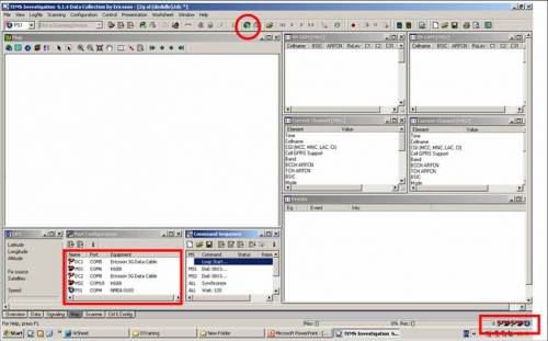
5. Make sure all equipments configured to the right port

6. Connect all godt-connecticon

godt--connectall

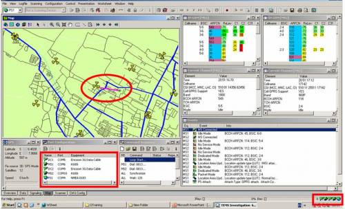
7. After all equipments connected (symbol green), window gps, serving neighbour gsm, current channel and events will be full filled

8. Don’t forget to lock TEMS Handset into GSM only or 3G only.

godt-workspace

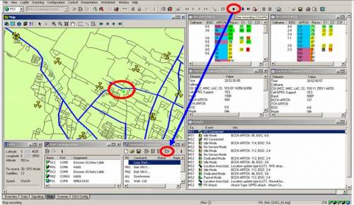
9. To start drive test, click record then start command sequence

godt-record

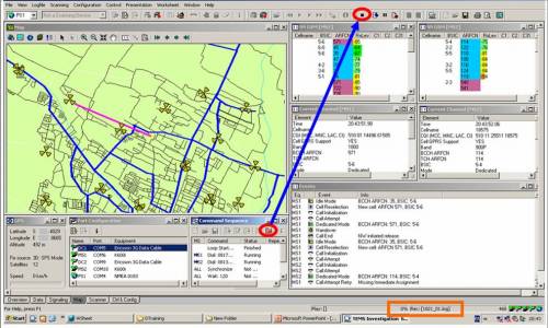
10. After all route complete, wait untill call end then stop command sequence and stop recording.

godt-stoprec

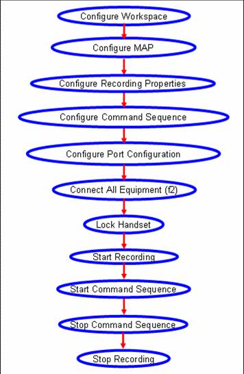
Here the flow step by step Go Drive Test !!!

godt-flow

command sequence in TEMS

Herewith the example of command sequence in TEMS

Voice Call CS

i.e “120/15” means 120 second on call then call end, 15 second wait and then call again.

1. Loop Start give the number of repetition for command below the loop start (General -> Loop Start)

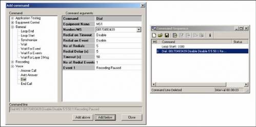
2. Dial select the MS and give the destination number (Voice -> Dial)

cs-ms1


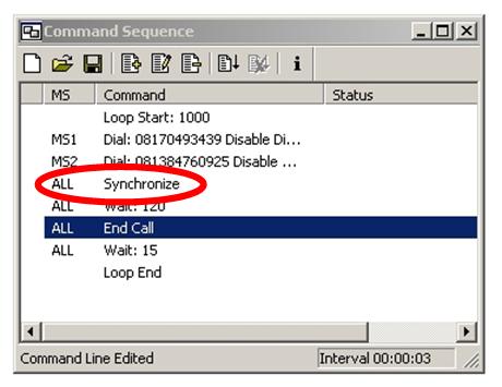
3. Synchronize to synchcronize MS before go to the next command (General -> Synchronize)
cs-sync

4. Wait 120 wait 120s on call (General -> Wait)

5. End Call (Voice -> End Call)

6. Wait 15 wait 15 before call again (General -> Wait)

7. Loop End (General -> Loop End)

Video Call CS

In general cs for video call is same as voice call, but in video call in dial command we must add “v”.

i.e

Loop Start

Dial v081384760975

Wait 120

End Call

Wait 15

Loop End

Drive Test Map Configurations

Create Geoset : Click Geoset Manager on Map window map-geoicon

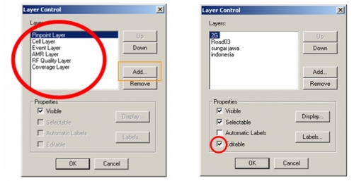
1. On layer control map-layericon remove all layer except Pinpoint, Cell, Event, AMR, RF Quality and Coverage layer

2. Add layer Route, Road, MCOM Site, and other *.tab

map-crtgeoset

3. Save Geoset

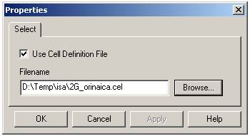
4. Load Cell file : Configuration -> General -> Cellfile Load

5. Use Cell Definition File then choose cell file

map-cell

6. ie. Map window configured

map-ie

My Headlines